(c) Adjusting the CCD unit
1.Remove original glass. (See Fig.
2.Remove the blind plate. (See Fig.
3.Place the CCD jig on CCD unit and loosen 3 screws.
4.Using the marks on the scanner base as a guide, adjust the CCD unit in either forward or backward direction.
The following table shows the error in the reproduction ratio between the copies and actual rulers compared to be measured, and the amount of adjustment of the CCD unit.
Amount of | Amount of | ||
error | adjustment | error | adjustment |
|
|
|
|
4.77 mm | 0.1% | ||
|
|
|
|
4.37 mm | 0.2% | ||
|
|
|
|
3.98 mm | 0.3% | ||
|
|
|
|
3.58 mm | 0.4% | ||
|
|
|
|
3.18 mm | 0.5% | ||
|
|
|
|
2.78 mm | 0.6% | ||
|
|
|
|
2.39 mm | 0.7% | ||
|
|
|
|
1.99 mm | 0.8% | ||
|
|
|
|
1.59 mm | 0.9% | ||
|
|
|
|
1.19 mm | 1.0% | ||
|
|
|
|
0.80 mm | 1.1% | ||
|
|
|
|
0.40 mm | 1.2% | ||
|
|
|
|
0.0% | 0.00 mm |
|
|
|
|
|
|
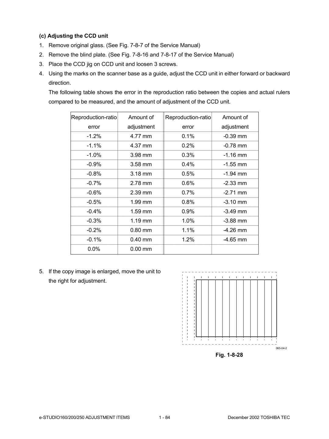
5.If the copy image is enlarged, move the unit to the right for adjustment.
065-04-2
Fig.
1 - 84 | December 2002 TOSHIBA TEC |