MMD-AP0181H, AP0241H, AP0271H MMD-AP0361H, AP0481H
MMD-AP0071SPH, AP0091SPH, AP0121SPH
MMC-AP0151H, AP0181H, AP0241H MMC-AP0271H, AP0361H, AP0481H
MML-AP0071H, AP0091H, AP0121H MML-AP0151H, AP0181H, AP0241H
Check of Concentration Limit
Contents
Explanation of indications
Explanation of illustrated marks
Confirmation of warning label on the main unit
Indication Explanation
∗ For details, refer to the parts list
Never recover the refrigerant into the outdoor unit
Do not modify the products
For spare parts, use those specified ∗
Check the following items after reinstallation
Metal section Earth position
Side
Limit even if the refrigerant leaks
Safety Caution Concerned to New Refrigerant
New Refrigerant R410A
Pipe Materials
Tools
Recharge of Refrigerant
Environmental concern
4mm-hexagonal wrench is required
Cylinder with siphon Cylinder without siphon
Operation mode
Operation mode Outline
Component Multi Using High-efficiency Refrigerant R410A
Outdoor units
Combination of outdoor units
Branching joints and headers
Flow selector units FS unit
Indoor units
RBM-Y1121FE
RBM-Y1801FE
MMD-AP0241H
Remote controllers
Indoor
Unit
Way
Air Discharge Cassette Type
AP0241WH, AP0271WH, AP0301WH AP0071WH, AP0091WH, AP0121WH
AP0481WH AP0151WH
AP0181WH
Indoor control P.C. board
Compact type
AP0071YH, AP0091YH, AP0121YH
Color
Indication
Symbol Parts name
Model MMU-AP0151SH, AP0181SH, AP0241SH
Network adapter
Option
Symbol Parts name
Way Air
Concealed
Duct Standard Type
AP0481BH, AP0561BH
AP0241BH
Symbol Parts name
Concealed Duct High Static Pressure Type
Model
MMD-AP0181H, AP0241H, AP0271H, AP0361H
Under
Ceiling Type
AP0241H, AP0271H, AP0361H
AP0151H, AP0181H
AP0121H, AP0151H, AP0181H, AP0241H
High Wall Type
Model MMK-AP0071H, AP0091H
Model MMK-AP0072H
AP0122H
AP0092H
Floor Standing Cabinet Type
AP0151H, AP0181H, AP0241H
Model MML-AP0071H, AP0091H, AP0121H
Color
Floor Standing Concealed Type
Model MML-AP0071BH, AP0091BH, AP0121BH
AP0151BH, AP0181BH, AP0241BH
Color indication
Symbol Parts name
AP0241H, AP0271H, AP0361H, AP0481H, AP0561H
Model MMF-AP0151H, AP0181H
Color
Model MMD-AP0071SPH
AP0091SPH, AP0121SPH,AP0151SPH
For undoor unit
Color indication
Outdoor Unit
Model MMY-MAP0801FT8
MAP1001FT8, MAP1201FT8
Parts layout
Flow Selector Unit FS
Model RBM-Y1122FE, Y1802FE, Y2802FE
Indoor Unit
Way Air Discharge Cassette Type
Way Air Discharge Cassette Compact type Type
Concealed Duct Standard Type
Concealed Duct High Static Pressure Type
Slim Duct Type
Under Ceiling Type
High Wall Type
Floor Standing Concealed Type
Floor Standing Cabinet Type
Floor Standing Type
Heat Recovery Model
Outdoor Control Unit
Flow Selector Unit FS Unit
MAP0802FT8 MAP1002FT8 MAP1202FT8
Parts Layout in Outdoor Unit
Front side Rear side
Indoor Unit
Name of Each Part
Sold Separately Parts
Outdoor Unit
Parts Name of Remote Controller
Display section
Correct Usage
Operation section
Preparation
Stop
Adjustment of Wind Direction
How to set up the air direction
How to start louvre swinging
How to stop louver swinging
How to set up the air flow direction
How to start swinging
How to stop swinging
Adjustment of air direction upward/downward
Right/Left air direction adjustment
Adjustment of air Flow direction Upwards/Downwards
Adjustment of air Flow direction rightwards/leftwards
Setup of air direction and swinging
Timer operation
Timer Operation
Cancel of timer operation
Installation
Maintenance
Cleaning the air inlet grille
Cleaning of main unit / remote controller
High Wall Type Model 1H series
Model 2H series
Air Conditioner Operations and Performance
When the Following Symptoms are Found
Re-Installation
Air conditioner operating conditions
Procedure Description
Confirmation of error history
Confirmation and check
Inverter Unit 8, 10, 12HP
Model MMY-MAP0802FT8, MAP1002FT8, MAP1202FT8
Explanation of Functional Parts
Functional part name Functional outline
Operation mode
Operation mode Outline
SVD
SVS
Svdd
Svss
TC2
TC1
TCJ
Selection of operation mode
Refrigerant Piping Systematic Diagram in System
ON-OFF list of Flow Selector Unit FS Unit valve
High outside temperature 10C or more Criterion
All cooling operation Operation of cooling only
Outdoor unit
Flow selector/Indoor unit Cooling thermo.-ON Stop
Low outside temperature 15C or less Criterion
OFF SV3E
Cooling thermo.-ON Stop
Flow selector/Indoor unit
All heating operation Operation of heating only
SV3B SV5 OFF SV3C SV6
Flow selector/Indoor unit Heating thermo.-ON
Heating thermo.-OFF
Mainly Cooling, Partly Heating Operation
Heating thermo.-ON
Outdoor unit Flow selector/Indoor unit
Mainly Heating, Partly Cooling Operation
Cooling thermo.-ON Heating thermo.-ON Stop
Defrost
Flow selector/Indoor unit Cooling thermo.-ON Others
Control Specifications
Outline of specifications Remarks
Remote controller Control outline Command
Allcooling All heating
Reset conditions
TC1
TCB-AX21E
Central control mode
Central control mode 1 Cannot operate
Central control mode 4 Cannot select mode
Operation Start/Operation End
Operation explanation and applied data, etc Remarks
Oil SV2
Operation explanation and applied data, etc Remarks
Operation explanation and applied data, etc Remarks
Ipdu
Cooling operation in low ambient temperatures
Other cautions
Release control list
PMV Pulse Motor Valve for outdoor unit
Oil equation control schematic diagram
Header outdoor unit MMY-MAP1202FT8 Unit to send oil
Follower outdoor unit MMY-MAP1202FT8 Unit to
Received oil
Procedure Execute the setup operation while the unit stops
Every pushing
Description At shipment
HEAT, Heat → Cool
Indoor unit capacity
Item code
How to Set Up the Cooling Only Indoor Unit
Setup data
Cooling Only setup Heat pump
Description
Setting When Connecting Multiple Indoor Units to a FS unit
Usage/Features
How to set up Item code
Push Vent + Test buttons simultaneously for Seconds or more
Case of not setting 01 to Item code 0E
SVS OFF
SVD OFF
SVD OFF Svdd SVS
Wiring and setup
Wiring diagram using remote control interface TCB-IFCB-4E
Applied Control in Indoor Unit
Remote location ON/OFF control box TCB-IFCB-4E
Ventilating fan control from remote controller
Wiring
Function
Operation
Using the timer time
Using the setup temp
Button, set to the setup data
Leaving-ON prevention control
Applied Control in Outdoor Unit
Outdoor fan High Static Pressure Shift
Outdoor unit interface P.C. board Connector position detail
Function Switch No Bit Connector No Used control P.C. board
Power Peak-cut Control Standard
Setup when Power peak-cut control requested
Relay contact capacity of operation port
Outdoor unit interface P.C. board
Power Peak-cut Control Expansion
Setup at power peak-cut control expansion request
SW1 SW2
CN513
Input signal Operation
Terminal Input signal Operation
Snowfall Fan Control
External master ON/OFF control
Operation Mode Selection Control
Night Operation Control
Cool OFF
Night operation sound Capacity Reduction dB a
Procedure and Summary of Test Operation
Main check items for electric wiring
Check Items before Test Operation
Case that a center control
Check list
Additional amount of refrigerant by pipe length
Corrective amount of refrigerant by system capacity
Additional amount of refrigerant
Check at Main Power-ON
Address Setup
Address Setup and Check Procedure
Check on outdoor unit
Address setup procedure
Address Setup Procedure
Line address switch on outdoor interface P.C. board
Turn on the power Wiring example in 2 lines
Operation procedure
Push SET button
Group address
Using Unit + SWING/FIX buttons, select the line Address
Using the setup temp
Using
Button to Operation procedure Confirm the changed contents
Push SET button to determine the setup data
Push Test button to finish the procedure
End
Displayed. Only fan of the selected indoor unit operates
Setup procedure
SW01 SW02 SW03 SW04
Troubleshooting in Test Operation
Check Code is Displayed on the Remote Controller
Check code
Cause Countermeasures
Remote Segment
Cause Countermeasures
Status Cause Countermeasures
Display
Incorrect wiring example Fig
Remote Header unit Incorrect example
Controller status Segment display
Status Incorrect example
Test Operation Check
Fan Operation Check
Cooling/Heating Test Operation Check
Test operation start/stop operation
Wireless remote controller
Turn OFF the power to the air conditioner
Button on the wireless remote controller
Test operation from outdoor unit
Procedure Description
Test cooling operation Test heating operation
Test operation
100
101
Service Support Function
Function Outline Setup/Release Segment display
Function to Start/Stop ON/OFF Indoor Unit from Outdoor Unit
102
Operation procedure
All cooling test operation function
All heating test operation function
103
Batch start/stop ON/OFF function
104
105
SW01 SW02 SW03 Units to be operated
Error Clearing Function
Error clearing in indoor unit
Method
Section a
Clearing from the interface P.C. board
Clearing of error check code by power reset
107
Distinction procedure
Remote Controller Distinction Function
108
Operation
Solenoid Valve Forced Open/Close Function in Outdoor Unit
Clear
110
Heater
Fan Operation Check in Outdoor Unit
111
SW01 SW02 SW03
Fan step
Release
Case to operate the fan in the erroneous outdoor unit only
Case to operate the fans in all the normal outdoor units
112
Manual Adjustment Function of Outside Temp to Sensor
Service support function list
Function contents
113
Indoor Fan Operation Check Function
Indoor Fan Only Operating Mode
114
Monitor Function of Remote Controller Switch
Contents
Procedure
Calling of display screen
Troubleshooting Summary
Before troubleshooting
Troubleshooting procedure
116
Check Method
Check code list
117
118
Error detected by TCC-LINK central control device
119
Main Outdoor 7-segment display Sensor block display
Device
New check code
Troubleshooting by Check Display on Remote Controller
Case of wired remote controller RBC-AMT31E
Confirmation of error history
Confirmation and check
Case of central remote controller TCB-SC642TLE
122
Case of AI-NET central remote controller
Error detection condition Check item position
124
Check code
Check code name
Error detection condition Check item position
Setup method of No. capacity-over detection
125
Convenient functions
126
Status Error detection condition Check item position
Outdoor 7-segment display
127
128
Detected Check code name
Error detection condition
129
Status
Check all the outdoor units in the corresponding line
130
Check code Detected Main Outdoor 7-segment display
131
Remote Central control Controller Check code
132
Name
133
Heating
134
Check code Status Error detection Check item position
Name Condition
135
Sub-code C
Sub-code D
Sub-code E
136 Error detected by TCC-LINK central control device
Error detected by AI-NET central control device
Error detection Check item position
Controller
How to check inverter output
How to check resistance of compressor winding
How to check the outdoor fan motor
137
Diagnosis Procedure for Each Check Code
138
139
E06
E07
Detected at outdoor side
140
141
E16
E18 / 97/99
E19
142
Indoor TCJ sensor error
Indoor TC2 sensor error
F03 Indoor TC1 sensor error
143
144
145
H02 / 1d Compressor error Lock
F31 / 1C
H01 / 1F
146
H14 Compressor 2 case thermo operation
147
H06 Low-pressure protective operation
148
Low oil level protection
Leakage check for SV3C valve
Clogging check for SV3E valve
149
TK3 temperature detective circuit error
150
151
L05
L03
L06
152
L18 / 8A Flow selector unit system error
153
L20
L28
L31 Extended IC error
P01 Indoor fan motor error
154
L30 / b6
P05 / AF Open phase, negative phase
155
P04 Actuation
High-pressure SW
P07 / 1C Heat sink overheat error
P10 / 0b Indoor overflow error
Indoor fan motor error
156
P13 Outdoor liquid back detection error 1. PMV1/PMV2 error
157
P15 / AE
Gas leak detection
P17 / bb Discharge temp TD2 error
158
P15 / AE Gas leak detection
TD condition Sub-code
P19 Way valve operation error
159
P20 High-pressure protective operation
Judgment criteria
P22 / 1A Outdoor fan Ipdu error
160
P26 Tr short-circuit protection error
Detective circuit error
161
P29 Compressor position
162
How to read the check display Segment display
Segment Display Function
Segment display on the outdoor unit Interface P.C. board
163
SW01 SW02 SW03 Display contents
164
165
166
SW03 SW02 Indoor address Segment display a
Sensor Characteristics
Temperature sensor characteristics
Outdoor Unit
Segment display A, B
Pressure sensor characteristics
Lead wire color
Indoor Unit
168
Pd sensor characteristics
Pressure Sensor Output Check
169
MPa Kg/cm²
Ps sensor characteristics
170
Flow Selector Unit FS Unit
171
May become
172
Detection Flow Almost normal Cooled
173
Reference
Refrigerant
Indoor Controller Block Diagram
Wired remote controller
Weekly timer
Series
Weekly timer
Wired remote controller Up to 2 units
175
Slim DuctType
176
Series
177
178
Wired remote controller
SlimDuctType
179
MCC-1402
Indoor P.C. Board
Type
181
Eeprom
Disp
CHK
MCC-1431-01
Flow Selector Unit P.C. Board
182
Optional Connector Specifications of Indoor P.C. Board
Function Connector Pin Specifications Remarks
183
DC12V COM
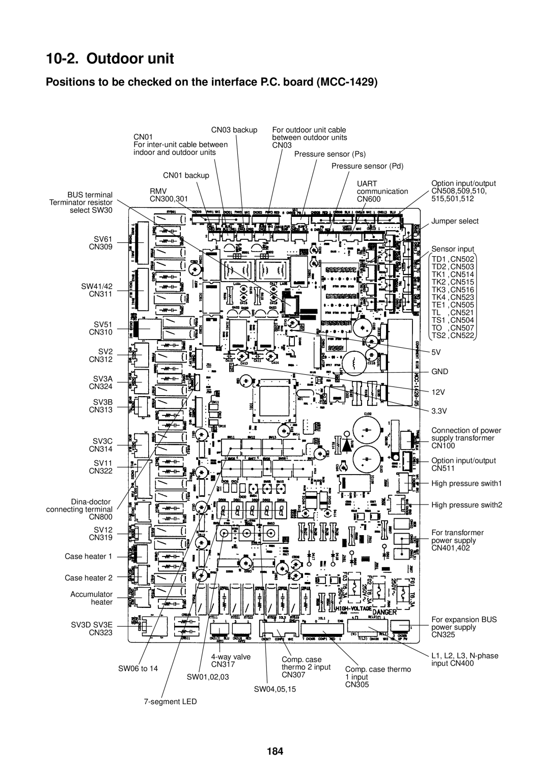
184
SV3D SV3E
Uart
RMV
Inverter P.C. board MCC-1502 IPDU1, IPDU2
185
Power supply P.C. board for fan MCC-1439
186
Part type Exchange contents
187
Before Backup Operation
Compressor Backup Setup
Procedure
Outline
Set up procedure for the malfunctioning outdoor unit
Backup Setup for Outdoor Unit
189
Operation procedure
Display example
Segment display oil level results
190
Refrigerant Recovery in the Malfunctioning Outdoor Unit
Before Refrigerant Recovery Operation
Refrigerant Recovery Procedure
Set up the malfunctioning outdoor unit as follows
Select an outdoor unit for pressure adjustment as follows
Set up all other outdoor units as follows
Setup for outdoor unit for adjustment of pressure
192
Set up the unit selected as the header unit as follows
Refrigerant recovery procedure backup
193
Setup for header unit
194
195
Refrigerant amount to be recovered = 37.5 28.0 = 9.5 kg
System Combination of outdoor units Refrigerant amount
Process after Repair
196
Trouble by leakage
197
Unit issuing Check code to be detected Phenomena
Check code Corresponding unit
198
Never recover the refrigerant into outdoor unit
Compressor Replacing Procedure Outline
199
Replacing Compressor
Exchanging a compressor
Removal of defective compressor
200
Color check of oil in the defective compressor
201
Measurement of oil amount in the normal compressor
Adjustment of oil amount in the service compressor
202
Installation of compressor
Vacuuming Case of single outdoor system
Case of multiple outdoor unit systems
Full opening of PMV1, PMV2
Check items Position Procedure
Procedure to Identify the Cause of Compressor Oil Shortage
204
Nitrogen
205
Pressure
Reassembly
206
Remarks
Disassembling
Work procedure Remarks
207
Fan motor
Part to be
Disassembling Example
208
Heat exchanger Right
Reassembly and cautions
209
Exchange of service P.C. board
Inverter assembly
210
211
Work procedure
Temperature Front side of air conditioner sensor posi
212
SV3C SV3A SV3B
213
Temperature Rear side of air conditioner
Used positions of SUS fixing band Total 5 positions
Assembly
214
215
Pull the accumulator upwards
216
Exchange procedure
Exchange of P.C. Board for Indoor Service
217
Procedure 1 Readout setup contents from Eeprom
Remote controller operation diagram
Procedure 2 Exchange of P.C. board for service
219
Procedure 3 Writing-in of setup contents to Eeprom
Eeprom layout
Type Indoor unit capacity Item code
221
How to Check Inverter Output
How to Check Outdoor Fan Motor
How to check resistance or compressor winding
Part name Procedure
How to Check Fan Power Supply P.C. Board and Fan Ipdu
How to check fan power supply P.C. board MCC-1439
How to check fan Ipdu
MCC-1439 Front View
Interface Board Replacement Procedure
Replacement steps
Dip Switch Setting contents
224
225
Comp-IPDU Board Replacement Procedure Manual
Comp-IPDU No SW801 Bit
COMP-IPDU No.1
226
COMP-IPDU No.2
Inverter Assembly Configuration
227
Toshiba Carrier Corporation