CNX System Administrator Guide
Aastra CNX hardware
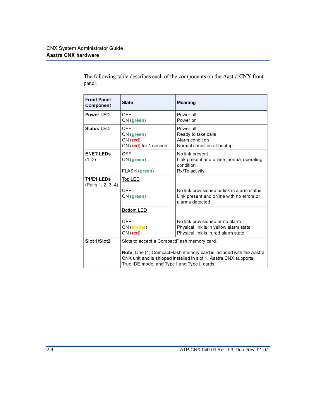
The following table describes each of the components on the Aastra CNX front panel.
Front Panel | State | Meaning | |
Component | |||
|
| ||
|
|
| |
Power LED | OFF | Power off | |
| ON (green) | Power on | |
Status LED | OFF | Power off | |
| ON (green) | Ready to take calls | |
| ON (red) | Alarm condition | |
| ON (red) for 1 second | Normal condition at bootup | |
ENET LEDs | OFF | No link present | |
(1, 2) | ON (green) | Link present and online: normal operating | |
|
| condition | |
| FLASH (green) | Rx/Tx activity | |
T1/E1 LEDs | Top LED |
| |
(Pairs 1, 2, 3, 4) | OFF | No link provisioned or link in alarm status | |
| |||
| ON (green) | Link present and online with no errors or | |
|
| alarms detected | |
|
|
| |
| Bottom LED |
| |
| OFF | No link provisioned or no alarm | |
| ON (amber) | Physical link is in yellow alarm state. | |
| ON (red) | Physical link is in red alarm state. | |
Slot 1/Slot2 | Slots to accept a CompactFlash memory card. | ||
| Note: One (1) CompactFlash memory card is included with the Aastra | ||
| CNX unit and is shipped installed in slot 1. Aastra CNX supports | ||
| True IDE mode, and Type I and Type II cards. | ||
|
|
| |