RS-485 Based Data Acquisition Control System
ADAM-5000 Series
Copyright Notice Acknowledgments
Message to the Customer
Advantech Customer Services
Technical Support
Product Warranty
Page
Contents
ADAM-5017H Analog Input Command Set
107
Power Supplies For relevant wiring issues
Figures
21 Dry contact signal input ADAM-5050
Figure A-1 Power supply connections
Figure F-11 System Shielding
Tables
Introduction
Introduction
Chapter
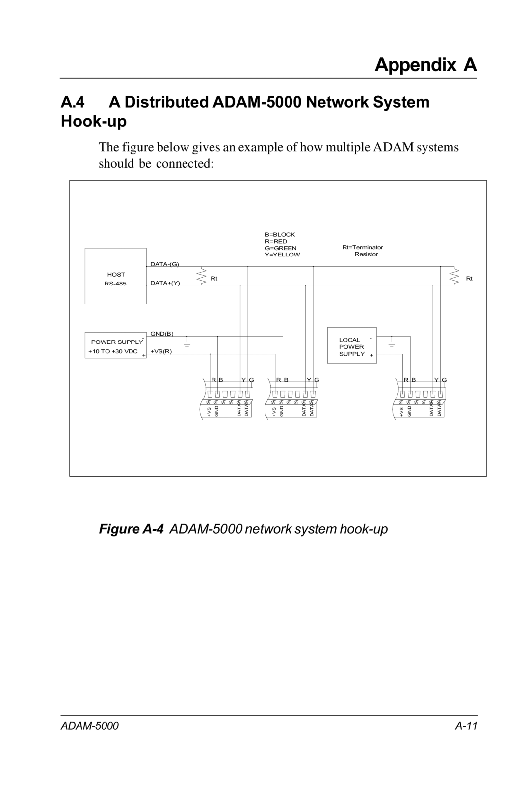
System Configuration
Few Steps to a Successful System
Installation Guideline
Power Requirements
Environmental Specifications
Diagnostic Indicators
General
ADAM-5000 Diagnostic indicators
Setting the Network Address Switch
ADAM-5000 Network address DIP switch
Dimensions and Weights ADAM-5000
Dimensions and Weights ADAM-5000E
Installation Guideline
Panel Mounting
Mounting
ADAM-5000 Rail mounting
DIN Rail Mounting
DC Power Supply Unit Wiring
Wiring and Connections
ADAM-5000 Wiring and connections
Modules Wiring
RS-485 Port Connection
RS-232 Port Connection
Built-in Communication Ports for Diagnostic Connection
Flexible Communication Port Function Connection
ADAM-5000 System
Overview
Major Features of the ADAM-5000 System
CPUs Basic Functions
Remote Software Configuration and Calibration
Way Isolation and Watchdog Timer
Flexible Alarm Setting
Diagnosis
Connectivity and Programming
Flexible Communication Port ADAM-5000E only
Flexible Communication Connection
Single System Setup thru the RS-232 Port
System Setup
Distributed I/O Setup thru the RS-485 Network
Processor
Technical Specifications of the ADAM-5000
Communication
Isolation
Basic Function Block Diagram
Modules
ADAM-5013 3-channel RTD input module
RTD Input Module
ADAM-5013
RTD inputs
Application wiring
Technical specifications of ADAM-5013
Applying calibration resistance
ADAM-5013 RTD Input Resistance Calibration
Calibration resistances ADAM-5013
ADAM-5017 8-channel analog input module
Analog Input Modules
ADAM-5017
V0+
Technical specifications of ADAM-5017
ADAM-5017H
ADAM-5017H 8-channel high speed analog input module
Application wiring V0+ MV/V V1+
Technical specifications of ADAM-5017H
ADAM-5018 7-channel thermocouple input module
ADAM-5018
Application wiring V0++ V1+
Analog Output Modules
Technical specifications of ADAM-5018
ADAM-5024 4-channel analog output module
ADAM-5024
Slew rate
Technical specifications of ADAM-5024
Application wiring I3+
Analog input module calibration
Analog I/O Modules Calibration
15 Zero calibration
Zero calibration and span calibration must be com
Calibration voltage ADAM-5017/5018
Calibration voltage ADAM-5017H
18 Output module calibration
Analog output module calibration
ADAM-5050 16-channel universal digital I/O module
Digital Input/Output Modules
ADAM-5050
19 Dip switch setting for digital I/O channel
22 Wet contact signal input ADAM-5050
ADAM-5051 16-channel digital input module
Technical specifications of ADAM-5050
ADAM-5051
25 TTL input ADAM-5051
Technical specifications of ADAM-5051
Overview Compatible ADAM-5000 Series Main Units
ADAM-5051D Module Diagram
ADAM-5051D 16-channel Digital Input W/ LED Module
Technical Specification of ADAM-5051/5051D
ADAM-5051D Application Wiring
ADAM-5052
ADAM-5052 8-channel isolated digital input module
ADAM-5056 16-channel digital output module
Technical specifications of ADAM-5052
ADAM-5056
33 Digital output used with SSR ADAM-5050/5056
Technical specifications of ADAM-5056
LED display
ADAM-5056D 16-channel Digital Output W/ LED Module
+Vss Limits current to 100 mA Power Ground
Main Units Supporting Digital Output Holding Function
ADAM-5056D Digital Output during Power-on and Reset
Technical Specification of ADAM-5056/5056D
ADAM-5060 relay output module
Relay Output Modules
ADAM-5060
ADAM-5068 relay output module
Technical specifications of ADAM-5060
ADAM-5068
39 Relay output
Technical specifications of ADAM-5068
ADAM-5080 4-channel Counter/Frequency Module
Counter/Frequency Module
ADAM-5080 Application Wiring
ADAM-5080 Module Diagram
42 TTL Input Level
ADAM-5080 Counter/Frequency Mode Selection
Up/Down Counting
Features -- Counter Mode
Bi-direction Counting
45 Wiring for Bi-direction Counting
Features -- Frequency Mode
Setting Initial Counter Value
Features -- Alarm Setting
48 Sending Alarm Signal recommended settings
Getting the Totalizer Value
Overflow Value
Example
Totalizer value = 10 0 + 1 x 4 + 10 -3 =
50 Digital Output Mapping
Features--Digital Output Mapping
51 Jumper Location on the ADAM-5080 Module
TTL/Isolated Input Level
ADAM-5080 Technical Specifications
Modules
Software Utilities
Main Menu
Adam Utility Software
Main screen
Setup
Setup options
System Setting
Output Data
Module Setting
File
Calibration
Terminal
Terminal emulation
Download Procedure New ADAM-5000/485 Firmware
Quit
DLL Dynamic Link Library Driver
DDE Dynamic Data Exchange Server
Overview Main Menu
ADAM-4000 and ADAM-5000 Windows Utility
Display the connected module
Save Function
Baud rate
COM Port Settings
Prefix Char
Search Connected modules
Timeout
Terminal Emulation
If you select the checksum function on previous
Connection for the Data Scope function
Data Scope
10 Monitor the issuing commands from PC#1
Saving a Module’s Configuration to File
Software Utilities
Load Module’s Configuration File
Software Utilities
Module Configuration
Software Utilities
Zero Calibration
Module Calibration
Span Calibration
Analog Input Resistance Calibration
CJC Calibration
Analog Output Calibration
Analog Output Module
Digital Output Module
Software Utilities
Digital Filter
Alarm Settings
Download Procedure
Choose the baud rate Choose Download file
Firmware download in progress Firmware download complete
Command Set
Syntax
Introduction
Command Syntax Main Unit #aaSiCj ADAM-5000 = 0 to ADAM-5000E
CPU
CPU Command Set
Name
Aannccff
Description
Syntax Aannccffcr
Baud rate codes
Example command %23000A40cr
Syntax $aa2cr
$aa2
Example command $452cr Response !450600cr
Syntax $aaMcr
$aaM
Example command $15Mcr Response !155000cr
Syntax $aaFcr
$aaF
Example command $17Fcr Response !17A1.06cr
Syntax $aaTcr
$aaT
Example command $12Tcr Response !1218245160cr
Syntax $aa5cr
$aa5
Example command $395cr
Syntax $aaEcr
$aaE
Example command $01Ecr Response !0100000001
Analog module error codes
ADAM-5013 RTD Input Command Set
Command Set RTD Input
Syntax $aaSiArrffcr
$aaSiArrff
Example command $35S3A2000cr
Syntax $aaSiBcr
$aaSiB
Example command $35S3Bcr Response !352000cr
$aaSi
Response Datadatadatacr if the command is valid
Syntax $aaSicr
Example command $35S3cr Response +80.01 +20.00 -40.12cr
Syntax $aaSiCjcr
$aaSiCj
Example command $35S3C0cr Response +80.01cr
Syntax $aaSiERcr
$aaSiER
Syntax $aaSi5mmcr
$aaSi5mm
$aaSi5mm
Example command $00S1501cr
Syntax $aaSi6cr
$aaSi6
Example command $00S16cr
Syntax $aaSi0cr
$aaSi0
Syntax $aaSi1cr
$aaSi1
Command Set RTD Input
Analog Input Command Set
Command Set 5017/5018 Analog Input
Example Command $35S3A0000cr
Returns the configuration status parameters for a
Example command $26S1B
Bit 7 cannot be enabled in the ADAM-5018 since
Example command $00S1581cr
$aaSi6
Example command $02S16cr
Syntax #aaSicr
#aaSi
Response Data data data data data data data data cr if
Chapter
Syntax #aaSiCjcr
#aaSiCj
Example command #22S2C2cr
Si identifies the I/O slot for which you wish to initialize
Syntax $aaSiØcr
$aaSiØ $aaSi0
Zero Calibration
Syntax $aaSi3cr
$aaSi3
Example command $09S13cr Response +0036.8cr
Syntax $aaSi9shhhhcr
$aaSi9shhhh
Example command $07S29+0042cr
ADAM-5017H Analog Input Command Set
Command Set 5017H Analog Input
Syntax $aaSiCjArrFF
$aaSiCjArrFF
Example command $35S3C1A0bFFcr
Syntax $aaSiCjB
$aaSiCjB
Example Command $35S3C1Bcr Response !350b00cr
Command Set 5017H Analog Input
Syntax $aaSiAFFff
$aaSiAFFff
Example command $35S3AFF00cr
Syntax $aaSiB
Example command $35S3Bcr Response !35FF00cr
Response Datadatadatadata datadatadatadatacr if
Syntax #aaSi
Ddddddddddddddddddddddddddddddddcrif
+8.125, +4.250, +10.000, +8.500, +7.675, +5.445
Returns the input value of a specified channel of a
Example command #35S3C2cr Response +9.750 cr
Analog Input Alarm Command Set
Syntax $aaSiCjAhscr
$aaSiCjAhs
Example command $03S0C1AHLcr
Syntax $aaSiCjAhcr
$aaSiCjAh
Example command $03S0C1ALcr
Syntax $aaSiCjAhEscr
$aaSiCjAhEs
Example command $03S0C1ALEEcr
Syntax $aaSiCjChcr
$aaSiCjCh
Example command $03S0C1CLcr
Syntax $aaSiCjAhCSkCncr
$aaSiCjAhCSkCn
$aaSiCjAhCSkCn$aaSiCjAhCSkCn
Example command $03S0C1ALCS1C0cr
Syntax $aaSiCjRhCcr
$aaSiCjRhC
Example command $03S0C1RLCcr Response !03S1C0cr
Syntax $aaSiCjAhUdatacr
$aaSiCjAhUdata
$aaSiCjAhUdata$aaSiCjAhUdata
Example command $03S0C1AHU+080.00cr
Syntax $aaSiCjRhUcr
$aaSiCjRhU
Example command $03S0C1RHUcr Response !03+2.0500cr
Syntax $aaSiCjScr
$aaSiCjS
Example command $03S0C1Scr
Analog Output Command Set
Command Set Analog Output
Other bits are not used and are set to
Syntax $aaSiCjArrffcr
Data format of 8-bit parameters
Example command $35S3C0A3110cr
Syntax $aaSiCjBcr
Example command $24S1C1B
Syntax #aaSiCjdatacr
#aaSiCjdata#aaSiCjdata
Example command #33S1C115.000cr
Syntax $aaSiCj4cr
$aaSiCj4
Example command $0AS1C14cr
Syntax $aaSiCj0cr
$aaSiCj0
100
Syntax $aaSiCj1cr
$aaSiCj1
102
Syntax $aaSiCj3hhcr
$aaSiCj3hh
Example command $07S1C2314cr
Syntax $aaSiCj6cr
$aaSiCj6
Example command $0AS2C16cr Response !0A03.000cr
Digital Input/Output Command Set
Aadataoutputdataoutput00cr if the command is
Response Aadatainputdatainput00cr if the command is valid
Example command $33S26cr Response !33112200cr
When writing to all channels byte 2 or 4-characters
When writing to a single channel bit the first character
#aaSiBBdata
Syntax #aaSiBBdatacr
Command #14S1001234cr
Example Command #15S11201cr
#aaSiBBdata#aaSiBBdata
Command #15S0003Acr
Syntax $aaSiMcr
$aaSiM
Example command $19S1Mcr Response !191322cr
ADAM-5080 Counter/Frequency Command Set
Counter
ADAM-5000 117
AaFFFFFFFFcr if the command is valid
ADAM-5000 119
Aa range 00-FF represents the 2-character
Response !18A2.3cr
Eample
Set Configuration
Example command $24S1A0002cr
124
Example command $35S3Bcr Response !350100cr
Response Data data data data cr if the command is valid
1235458013267521306934521463051832106549cr
Example command #16S2cr
1235458013, 2675213069, 3452146305
0e88fa63c33697b52a68d61fe2ca6915cr
0000098700,0000064900,0000076200,0000011600
0000098700000006490000000762000000011600cr
Actual frequency = 98700/100 =
0000F1000002000000031000000DD400cr
Read One Channel Counter Frequency Data
Example command $35S3C2cr Response 0000000451cr
Syntax $aaSiØdatacr
$aaSiØdata
Example command $26S3000765cr
$aaSiØ
Example command $26S30cr Response !2600765cr
Syntax $aaSiCj5scr
$aaSiCj5s
Example command $26S3C251cr
Syntax $aaSiCj5cr
$aaSiCj5
Example command $26S3C25cr
Clear Counter
Example command $26S3C26cr response !26cr
Syntax $aaSi7cr
$aaSi7
Example command $26S37cr Response !2600000001cr
Syntax @aaSiCjPdatacr
@aaSiCjPdata@aaSiCjPdata
@aaSiCjPdata
Example command @26S3C2P0000004369cr
Syntax @aaSiCjGcr
@aaSiCjG
Example command @26S3C2Gcr Response !260000004369cr
Set Alarm Disable/Latch
Example command $03S0C1ALEDcr
Read Alarm Disable/Latch
150
Clear Alarm Status
152
Connect the High/Low alarm of the specified input
154
Return the High/Low alarm limit output connection of a
Example command $03S0C1RLCcr Response !03SØC1cr
Set the High/Low alarm limit value for the specified input
Example command $03SØC1AHU0000000020cr response !03cr
Return the High/Low alarm limit value for the specified
Example command $03SØC1RHUcr response !030000000026cr
Read whether an alarm occurred for the specified input
Example command $03SØC1S
Troubleshooting
Hardware Diagnosis
Diagnosis
Software Diagnosis
PWR Indicator
System Indicators
Faulty Power Supply
Incorrect External Power
Device or Module causing Power Supply to Shutdown
RUN Indicator
Communication Problems
Some Quick Steps
I/O Module Troubleshooting
Quick Start Example
System Requirements to Setup an ADAM-5000 System
Host Computer
Power Supply
COM
Communication Wiring
Adam Utility Software
Basic Configuration Hook-up
Adam Isolated RS-232/RS-485 Converter optional
Adam Repeater optional
Configuration with the Adam Utility Software
Default Factory Settings
Example
Configuration with the Adam Command Set
Baud Rate and Checksum
Changing Baud Rate and Checksum
GND
Figure A-4 ADAM-5000 network system hook-up
Distributed ADAM-5000 Network System Hook-up
This page intentionally left blank
Data Formats and I/O Ranges
Engineering Units
Analog Input Formats
Appendix B
Analog Input Ranges ADAM-5017
Complement Engineering +100.00 ±000.00 10 µV Units
0000
Analog Input Ranges of ADAM-5017H
Analog Output Ranges
Analog Output Formats
ADAM-5013 RTD Input Format and Ranges
Data Formats and I/O Ranges
RS-485 Network
RS-485 Network
Daisychain
Basic Network Layout
Figure C-2 Star structure
Star Layout
Figure C-3 Random structure
Random
Figure C-4 ADAM-4000 and ADAM-5000 in a network
Line Termination
Figure C-5 Signal distortion
Figure C-6 Termination resistor locations
Intelligent RS-485 Control
RS-485 Data Flow Control
This page intentionally left blank
How to Use the Checksum Feature
Example
Checksum Enable/Disable
Appendix D
Printable Ascii Characters
Appendix E ADAM-4000/5000 System Grounding Installation
Grounding Installation
ADAM-4000/5000 System Grounding Installation
Requirements for RS-485 signal wires
External DI, DO, AI, AO Wiring Reference
Figure E-4 Grounding for signal wires
Figure E-5 Grounding Reference
Some Suggestions on Wiring Layout
Appendix F Grounding Reference
ADAM-5000
‘Earth’ for reference
Grounding
Figure F-2 Grounding Bar
‘Frame Ground’ and ‘Grounding Bar’
Figure F-3 Normal mode and Common mode
Normal Mode and Common Mode
Figure F-4 Normal mode and Common mode
Figure F-5 The purpose of high voltage transmission
Wire impedance
Figure F-7 Single point groundinF
Single Point Grounding
Cable Shield
Shielding
Figure F-10 Double isolated cable
Figure F-11 System Shielding
System Shielding
Figure F-12 The characteristic of the cable
Figure F-13 System Shielding
Noise Reduction Techniques
Figure F-15 Noise Reduction Techniques
Check Point List
Grounding Reference