Chapter 4 Parameters
This parameter is to set V/F curve. If this parameter isn’t set to 00, parameter
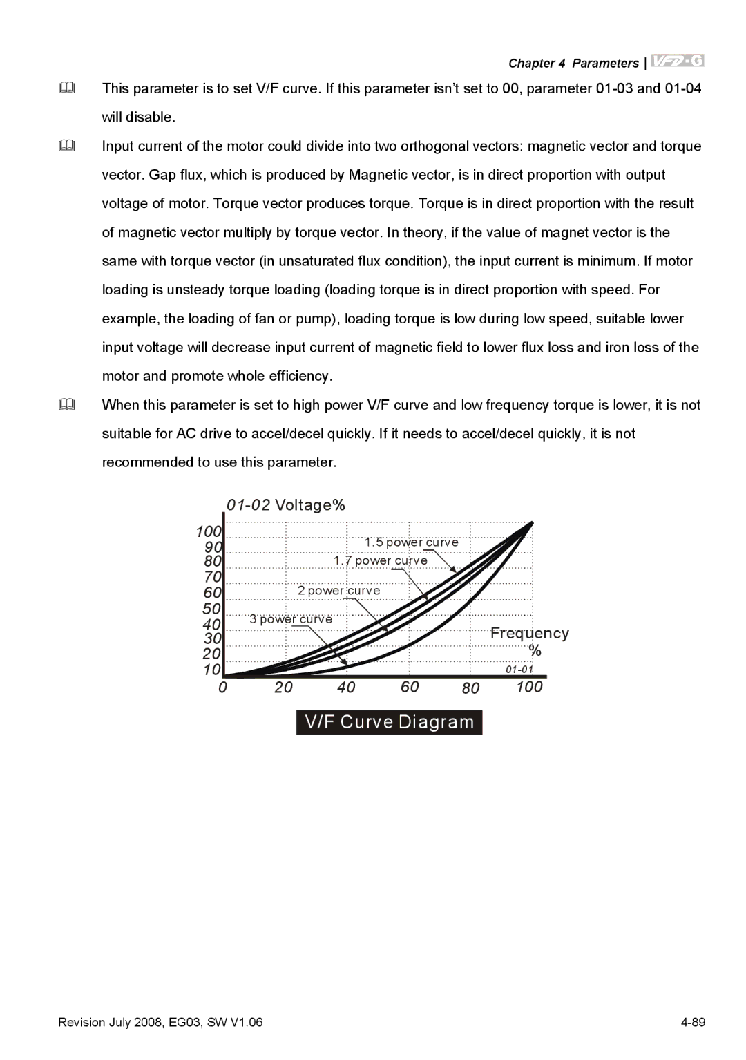
Input current of the motor could divide into two orthogonal vectors: magnetic vector and torque vector. Gap flux, which is produced by Magnetic vector, is in direct proportion with output voltage of motor. Torque vector produces torque. Torque is in direct proportion with the result of magnetic vector multiply by torque vector. In theory, if the value of magnet vector is the same with torque vector (in unsaturated flux condition), the input current is minimum. If motor loading is unsteady torque loading (loading torque is in direct proportion with speed. For example, the loading of fan or pump), loading torque is low during low speed, suitable lower input voltage will decrease input current of magnetic field to lower flux loss and iron loss of the motor and promote whole efficiency.
When this parameter is set to high power V/F curve and low frequency torque is lower, it is not suitable for AC drive to accel/decel quickly. If it needs to accel/decel quickly, it is not recommended to use this parameter.
| |
100 | 1.5 power curve |
90 |
801.7 power curve
70
602 power curve
50 | 3 power curve |
40 | |
30 | Frequency |
20 | % |
10 |
0 20 40 60 80 100
V/F Curve Diagram
Revision July 2008, EG03, SW V1.06 |