Chapter 4 Parameters
3.2ADR (communication address)
Valid communication addresses are in the range of 0 to 254. a communication address equal to 0, means broadcast to all AC drives (AMD). In this case, the AMD will not reply any message to the master device.
For example, communication to AMD with address 16 decimal: ASCII mode: (ADR 1, ADR 0) = ’1’,’0’ => ‘1’=31H, ‘0’=30H RTU mode: (ADR) = 10H
3.3CMD (command code) and DATA (data character)
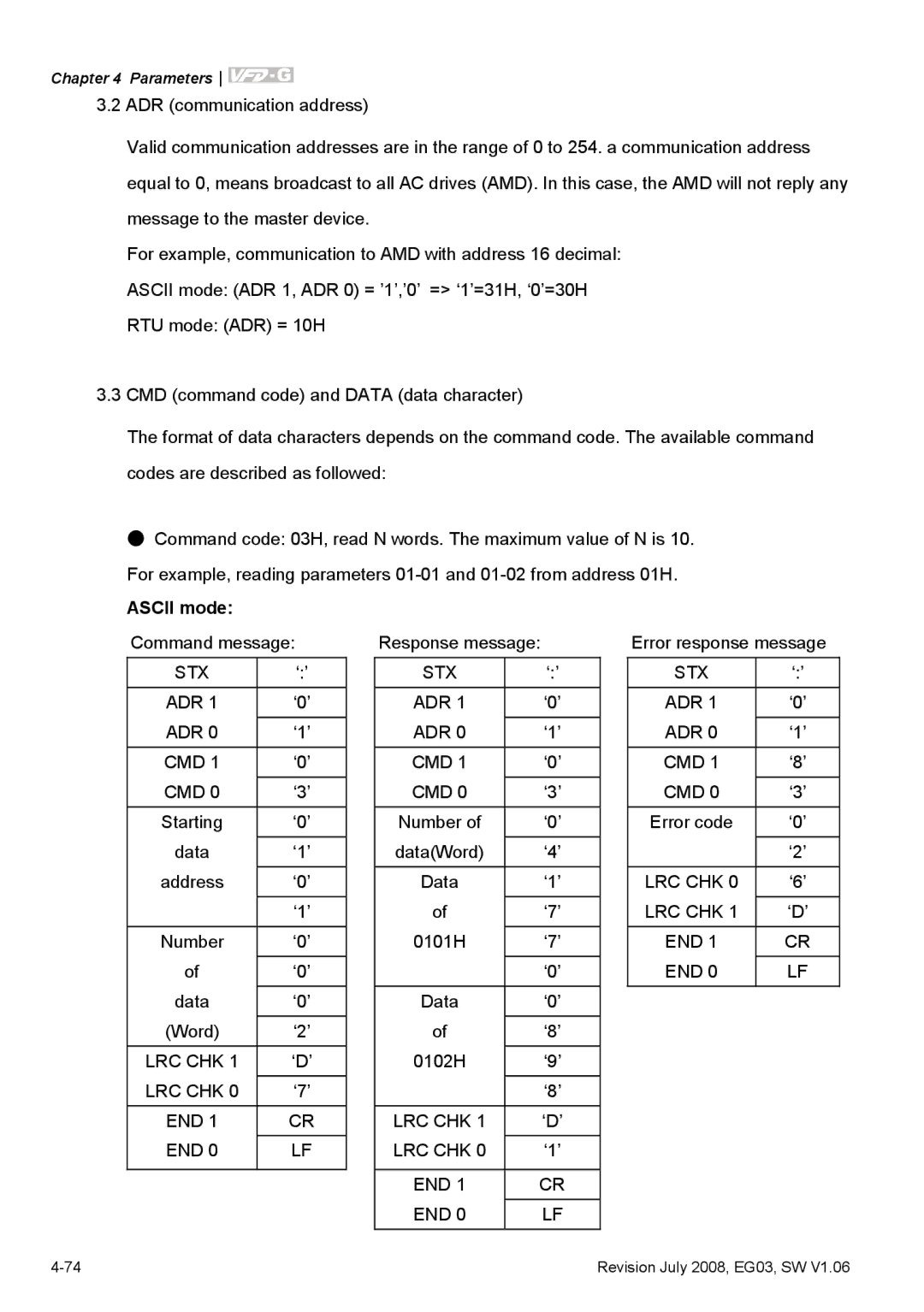
The format of data characters depends on the command code. The available command codes are described as followed:
●Command code: 03H, read N words. The maximum value of N is 10. For example, reading parameters
ASCII mode: |
|
|
|
|
|
|
|
Command message: |
| Response message: |
| Error response message | |||
STX | ‘:’ |
| STX | ‘:’ |
| STX | ‘:’ |
ADR 1 | ‘0’ |
| ADR 1 | ‘0’ |
| ADR 1 | ‘0’ |
|
|
|
|
|
|
|
|
ADR 0 | ‘1’ |
| ADR 0 | ‘1’ |
| ADR 0 | ‘1’ |
|
|
|
|
|
|
|
|
CMD 1 | ‘0’ |
| CMD 1 | ‘0’ |
| CMD 1 | ‘8’ |
CMD 0 | ‘3’ |
| CMD 0 | ‘3’ |
| CMD 0 | ‘3’ |
Starting | ‘0’ |
| Number of | ‘0’ |
| Error code | ‘0’ |
|
|
|
|
|
|
|
|
data | ‘1’ |
| data(Word) | ‘4’ |
|
| ‘2’ |
address | ‘0’ |
| Data | ‘1’ |
| LRC CHK 0 | ‘6’ |
|
|
|
|
|
|
|
|
| ‘1’ |
| of | ‘7’ |
| LRC CHK 1 | ‘D’ |
|
|
|
|
|
|
|
|
Number | ‘0’ |
| 0101H | ‘7’ |
| END 1 | CR |
of | ‘0’ |
|
| ‘0’ |
| END 0 | LF |
|
|
|
|
|
|
|
|
data | ‘0’ |
| Data | ‘0’ |
|
|
|
|
|
|
|
|
|
|
|
(Word) | ‘2’ |
| of | ‘8’ |
|
|
|
LRC CHK 1 | ‘D’ |
| 0102H | ‘9’ |
|
|
|
|
|
|
|
|
|
|
|
LRC CHK 0 | ‘7’ |
|
| ‘8’ |
|
|
|
|
|
|
|
|
|
|
|
END 1 | CR |
| LRC CHK 1 | ‘D’ |
|
|
|
END 0 | LF |
| LRC CHK 0 | ‘1’ |
|
|
|
|
|
|
|
|
|
|
|
|
|
| END 1 | CR |
|
|
|
|
|
|
|
|
|
|
|
|
|
| END 0 | LF |
|
|
|
Revision July 2008, EG03, SW V1.06 |