Chapter 4 Parameters |
|
|
|
|
|
|
|
|
|
| |
|
|
|
|
|
|
|
|
|
| ||
| LRC CHK 1 |
| ‘9’ |
|
|
|
|
|
|
| |
| LRC CHK 0 |
| ‘A’ |
|
|
|
|
|
|
| |
| END 1 | CR |
|
|
|
|
|
|
| ||
| END 0 |
| LF |
|
|
|
|
|
|
| |
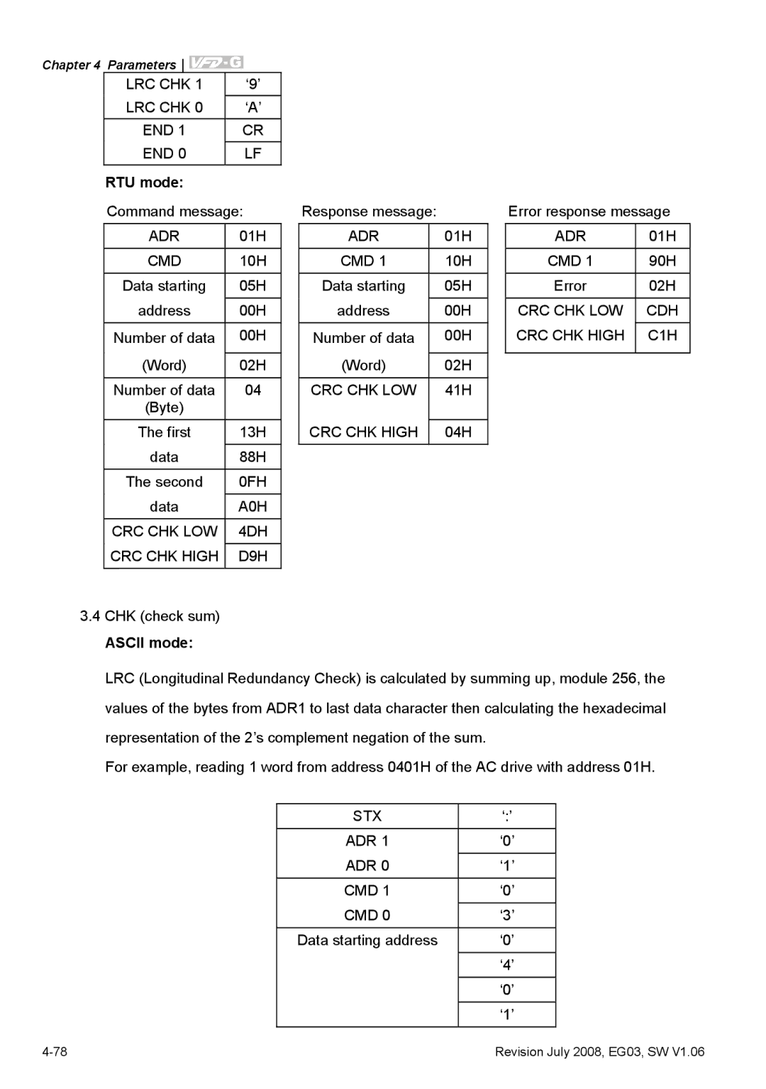
| RTU mode: |
|
|
|
|
|
|
|
|
| |
| Command message: |
| Response message: |
|
| Error response message | |||||
| ADR | 01H |
| ADR |
| 01H |
| ADR | 01H | ||
|
|
|
|
|
|
|
|
|
| ||
| CMD | 10H |
| CMD 1 |
| 10H |
| CMD 1 | 90H | ||
| Data starting | 05H |
| Data starting |
| 05H |
| Error | 02H | ||
| address | 00H |
| address |
| 00H |
| CRC CHK LOW | CDH | ||
| Number of data | 00H |
| Number of data |
| 00H |
| CRC CHK HIGH | C1H | ||
|
|
|
|
|
|
|
|
|
| ||
| (Word) | 02H |
| (Word) |
| 02H |
|
|
| ||
| Number of data | 04 |
| CRC CHK LOW |
| 41H |
|
|
| ||
| (Byte) |
|
|
|
|
|
|
|
|
| |
| The first | 13H |
| CRC CHK HIGH |
| 04H |
|
|
| ||
| data | 88H |
|
|
|
|
|
|
| ||
| The second | 0FH |
|
|
|
|
|
|
| ||
|
|
|
|
|
|
|
|
|
| ||
| data | A0H |
|
|
|
|
|
|
| ||
| CRC CHK LOW | 4DH |
|
|
|
|
|
|
| ||
| CRC CHK HIGH | D9H |
|
|
|
|
|
|
| ||
|
|
|
|
|
|
|
|
|
|
|
|
3.4CHK (check sum)
ASCII mode:
LRC (Longitudinal Redundancy Check) is calculated by summing up, module 256, the values of the bytes from ADR1 to last data character then calculating the hexadecimal representation of the 2’s complement negation of the sum.
For example, reading 1 word from address 0401H of the AC drive with address 01H.
STX | ‘:’ |
ADR 1 | ‘0’ |
ADR 0 | ‘1’ |
CMD 1 | ‘0’ |
CMD 0 | ‘3’ |
|
|
Data starting address | ‘0’ |
| ‘4’ |
| ‘0’ |
|
|
| ‘1’ |
Revision July 2008, EG03, SW V1.06 |