Chapter 4 Parameters
Group 2: Operation Method Parameters
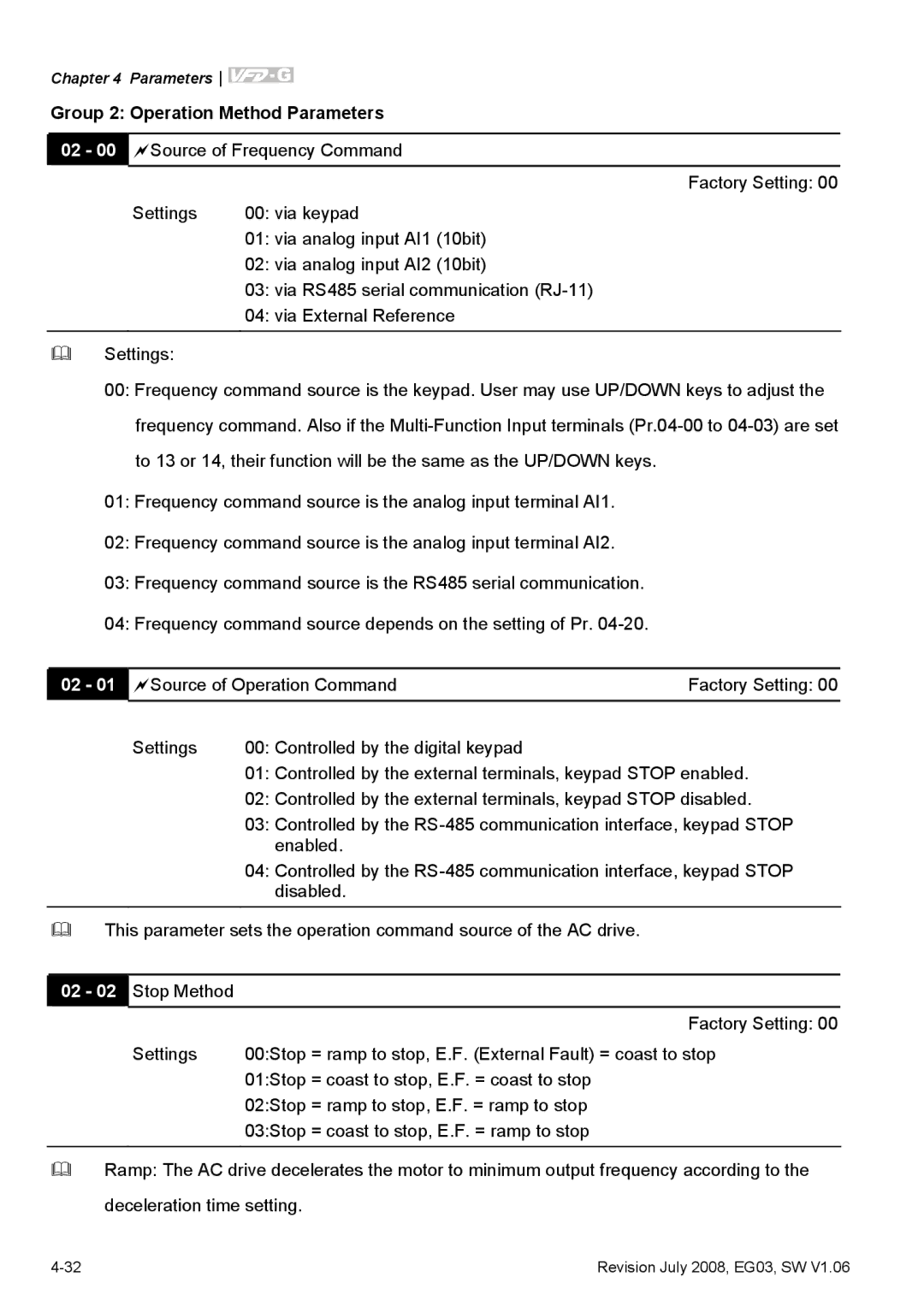
02 - 00 Source of Frequency Command
Factory Setting: 00
Settings | 00: via keypad |
| 01: via analog input AI1 (10bit) |
| 02: via analog input AI2 (10bit) |
| 03: via RS485 serial communication |
| 04: via External Reference |
|
|
Settings: |
|
00:Frequency command source is the keypad. User may use UP/DOWN keys to adjust the frequency command. Also if the
01:Frequency command source is the analog input terminal AI1.
02:Frequency command source is the analog input terminal AI2.
03:Frequency command source is the RS485 serial communication.
04:Frequency command source depends on the setting of Pr.
02 - 01 | Source of Operation Command | Factory Setting: 00 | |
| Settings | 00: Controlled by the digital keypad |
|
01:Controlled by the external terminals, keypad STOP enabled.
02:Controlled by the external terminals, keypad STOP disabled.
03:Controlled by the
04:Controlled by the
This parameter sets the operation command source of the AC drive.
02 - 02 Stop Method
| Factory Setting: 00 |
Settings | 00:Stop = ramp to stop, E.F. (External Fault) = coast to stop |
| 01:Stop = coast to stop, E.F. = coast to stop |
| 02:Stop = ramp to stop, E.F. = ramp to stop |
| 03:Stop = coast to stop, E.F. = ramp to stop |
|
|
Ramp: The AC drive decelerates the motor to minimum output frequency according to the
deceleration time setting.
Revision July 2008, EG03, SW V1.06 |
