| Chapter 4 Parameters |
| |
|
| ||
Number of data | ‘0’ |
|
|
| ‘0’ |
|
|
|
|
|
|
| ‘0’ |
|
|
| ‘1’ |
|
|
LRC CHK 1 | ‘F’ |
|
|
|
|
|
|
LRC CHK 0 | ‘6’ |
|
|
END 1 | CR |
|
|
END 0 | LF |
|
|
|
|
|
|
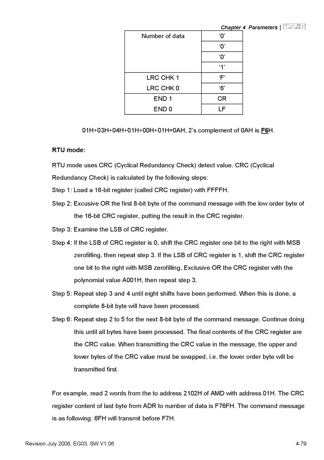
01H+03H+04H+01H+00H+01H=0AH, 2’s complement of 0AH is F6H.
RTU mode:
RTU mode uses CRC (Cyclical Redundancy Check) detect value. CRC (Cyclical Redundancy Check) is calculated by the following steps:
Step 1: Load a
Step 2: Excusive OR the first
Step 3: Examine the LSB of CRC register.
Step 4: If the LSB of CRC register is 0, shift the CRC register one bit to the right with MSB zerofilling, then repeat step 3. If the LSB of CRC register is 1, shift the CRC register one bit to the right with MSB zerofilling, Exclusive OR the CRC register with the polynomial value A001H, then repeat step 3.
Step 5: Repeat step 3 and 4 until eight shifts have been performed. When this is done, a complete
Step 6: Repeat step 2 to 5 for the next
For example, read 2 words from the to address 2102H of AMD with address 01H. The CRC register content of last byte from ADR to number of data is F76FH. The command message is as following. 6FH will transmit before F7H.
Revision July 2008, EG03, SW V1.06 |
