Chapter 4 Parameters
02 - 07 Reserved
02 - 08
Factory Setting: 00
Settings | Bit0~1: 00 | = F LED | |
| 01 | = H LED | |
| 10 | = U LED (special display) | |
| 11 | = Fwd / Rev | |
| Bit2: 0 = Fwd LED / 1 = Rev LED | ||
| Bit3~5: 000 = 1st | ||
| 001 | = 2nd | |
| 010 | = 3rd | |
| 011 | = 4th | |
| 100 | = 5th | |
| Bit6~7: Reserved | ||
|
|
|
|
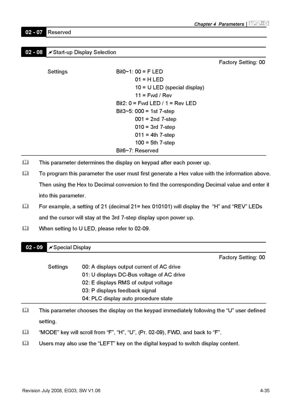
This parameter determines the display on keypad after each power up.
To program this parameter the user must first generate a Hex value with the information above.
Then using the Hex to Decimal conversion to find the corresponding Decimal value and enter it
into this parameter.
For example, a setting of 21 (decimal 21= hex 010101) will display the “H” and “REV” LEDs
and the cursor will stay at the 3rd
When setting to U LED, please refer to
02 - 09 Special Display
Factory Setting: 00
Settings | 00: A displays output current of AC drive |
| 01: U displays |
| 02: E displays RMS of output voltage |
| 03: P displays feedback signal |
| 04: PLC display auto procedure state |
|
|
This parameter chooses the display on the keypad immediately following the “U” user defined
setting.
“MODE” key will scroll from “F”, “H”, “U”, (Pr.
Users may also use the “LEFT” key on the digital keypad to switch display content.
Revision July 2008, EG03, SW V1.06 |
