Chapter 4 Parameters
Group 10: PID Control Parameters
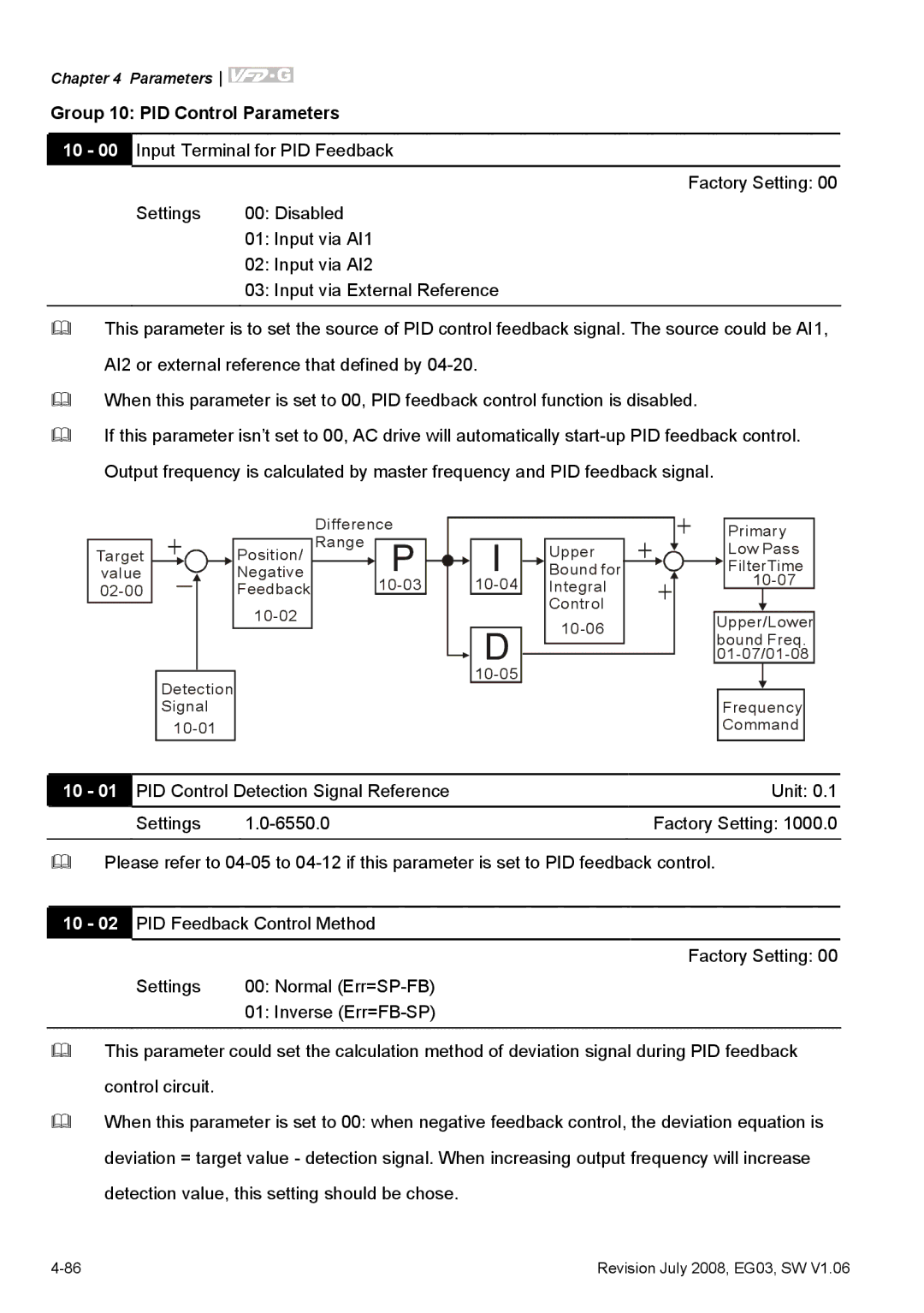
10 - 00 Input Terminal for PID Feedback
Factory Setting: 00
Settings | 00: Disabled |
| 01: Input via AI1 |
| 02: Input via AI2 |
| 03: Input via External Reference |
|
|
This parameter is to set the source of PID control feedback signal. The source could be AI1, AI2 or external reference that defined by
When this parameter is set to 00, PID feedback control function is disabled.
If this parameter isn’t set to 00, AC drive will automatically
| + |
|
|
|
|
| Difference |
|
|
|
|
|
|
|
| |||
Target |
|
|
|
| Position/ | Range | P |
|
| I |
| Upper | + |
|
| |||
|
|
|
|
|
| |||||||||||||
value |
|
|
|
|
|
|
| Negative |
|
|
|
| Bound for |
|
|
| ||
|
|
|
|
|
|
| Feedback |
|
| Integral | + |
| ||||||
|
|
|
|
|
|
|
|
|
| |||||||||
|
|
|
|
|
|
|
|
|
|
|
|
|
| Control |
|
|
| |
|
|
|
|
|
|
|
|
|
|
|
| D |
|
|
| |||
|
|
|
|
|
|
|
|
|
|
|
|
|
|
|
| |||
|
|
|
|
|
|
|
|
|
|
|
|
|
|
|
|
|
| |
|
|
|
|
|
|
|
|
|
|
|
|
|
|
|
|
|
| |
| Detection |
|
|
|
|
|
|
|
| |||||||||
|
|
|
|
|
|
|
|
|
|
|
| |||||||
| Signal |
|
|
|
|
|
|
|
|
|
|
| ||||||
|
|
|
|
|
|
|
|
|
|
|
|
| ||||||
+
Primary
Low Pass
![]() FilterTime
FilterTime
Upper/Lower bound Freq.
Frequency Command
10 - 01 | PID Control Detection Signal Reference | Unit: 0.1 | |
| Settings | Factory Setting: 1000.0 | |
|
| ||
Please refer to | |||
|
|
| |
10 - 02 | PID Feedback Control Method |
| |
|
|
| Factory Setting: 00 |
| Settings | 00: Normal |
|
|
| 01: Inverse |
|
|
|
|
|
This parameter could set the calculation method of deviation signal during PID feedback control circuit.
When this parameter is set to 00: when negative feedback control, the deviation equation is deviation = target value - detection signal. When increasing output frequency will increase detection value, this setting should be chose.
Revision July 2008, EG03, SW V1.06 |