Chapter 2 Installation and Wiring![]()
![]()
![]()
![]()
![]()
Terminal | Terminal Function | Factory Settings |
Symbol |
|
|
+12V/ACM | Potentiometer power source | +12Vdc 20mA (Variable Resistor: 3~5KΩ) |
|
|
|
|
| 0~10V/0~1A correspond to 0~Max. operation frequency |
AI1 | Analog voltage/current Input | Resolution: 10 bits |
|
| Function: |
|
|
|
|
| 0~10V/0~1A correspond to 0~Max. operation frequency |
AI2 | Analog voltage/current Input | Resolution: 10 bits |
|
| Funciton: |
|
|
|
AC1/AC2 | Analog control signal common | Used as common for analog inputs. |
|
|
|
NOTE: Control signal wiring size: 18 AWG (0.75 mm2) with shielded wire.
Analog inputs (AI1, AI2, AC1, AC2)
Analog input signals are easily affected by external noise. Use shielded wiring and keep it as short as possible (<20m) with proper grounding. If the noise is inductive, connecting the shield to terminal AC1/AC2 can bring improvement.
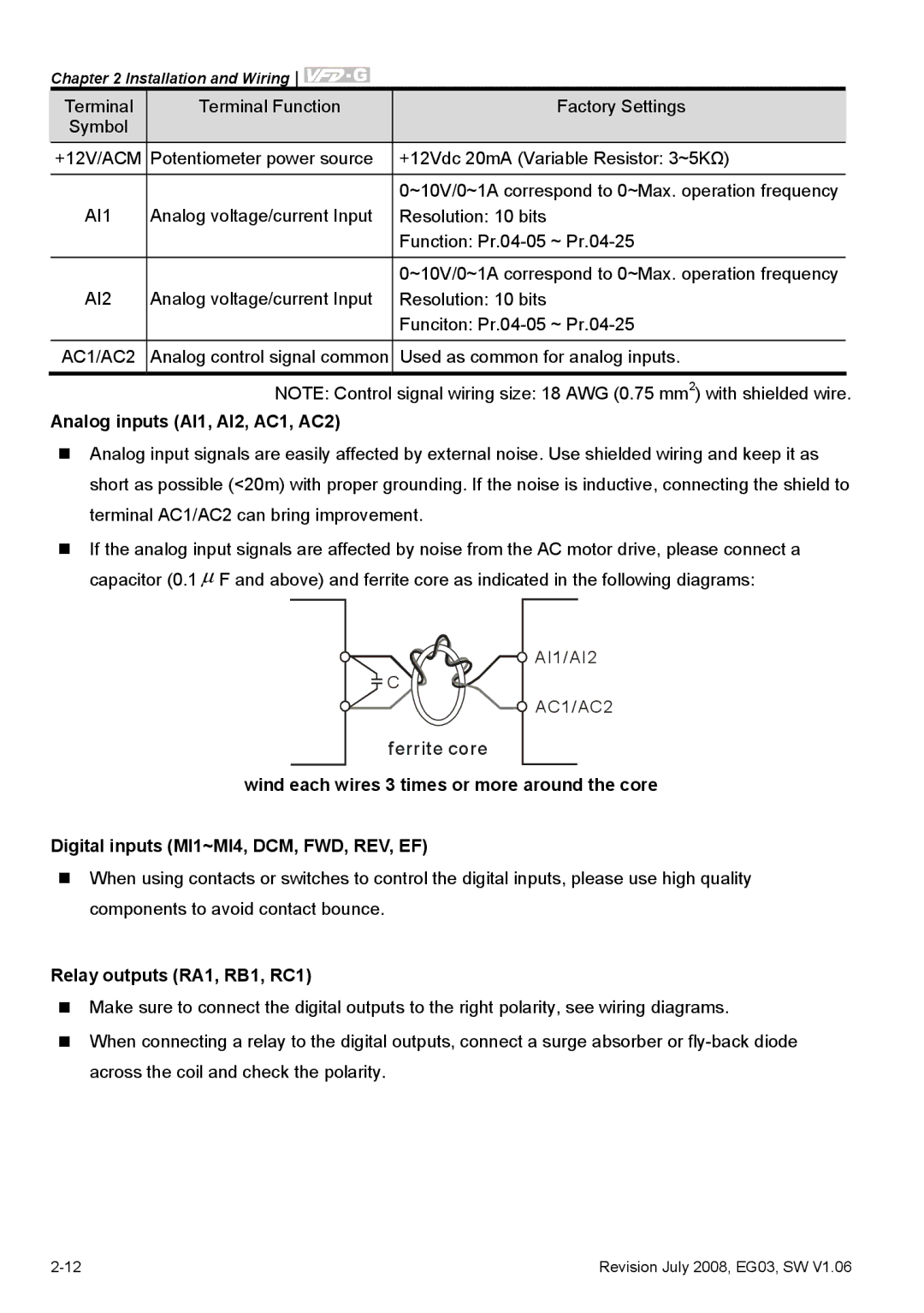
If the analog input signals are affected by noise from the AC motor drive, please connect a capacitor (0.1 μ F and above) and ferrite core as indicated in the following diagrams:
![]() AI1/AI2
AI1/AI2
![]() C
C
![]() AC1/AC2
AC1/AC2
ferrite core
wind each wires 3 times or more around the core
Digital inputs (MI1~MI4, DCM, FWD, REV, EF)
When using contacts or switches to control the digital inputs, please use high quality components to avoid contact bounce.
Relay outputs (RA1, RB1, RC1)
Make sure to connect the digital outputs to the right polarity, see wiring diagrams.
When connecting a relay to the digital outputs, connect a surge absorber or
Revision July 2008, EG03, SW V1.06 |