Chapter 4 Parameters

H ![]()
|
|
|
|
|
|
|
|
|
|
| |
|
|
|
|
|
|
|
|
|
| F | |
| 04 | 01 | |||||||||
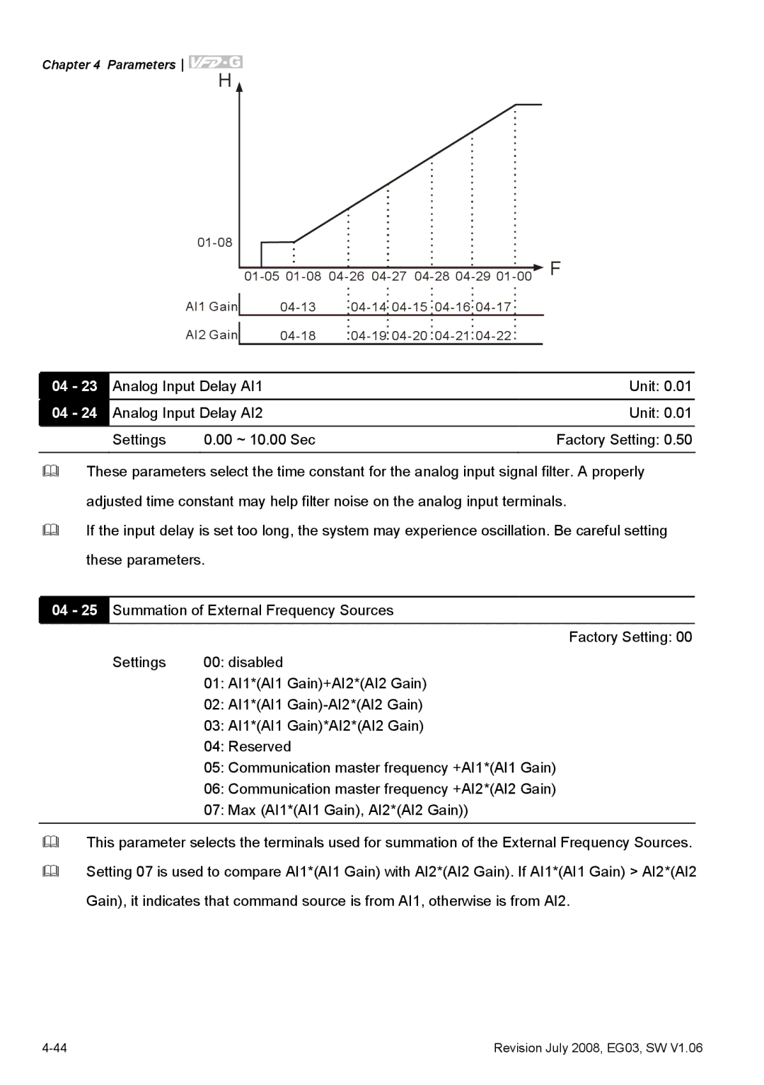
AI1 Gain | 04 | 04 | 04 |
|
|
| |||||
AI2 Gain | 04 | 04 | 04 |
|
|
| |||||
04 - 23 | Analog Input Delay AI1 | Unit: 0.01 | |
04 - 24 | Analog Input Delay AI2 | Unit: 0.01 | |
| Settings | 0.00 ~ 10.00 Sec | Factory Setting: 0.50 |
|
|
|
|
These parameters select the time constant for the analog input signal filter. A properly
adjusted time constant may help filter noise on the analog input terminals.
If the input delay is set too long, the system may experience oscillation. Be careful setting
these parameters.
04 - 25 Summation of External Frequency Sources
Factory Setting: 00
Settings | 00: disabled |
| 01: AI1*(AI1 Gain)+AI2*(AI2 Gain) |
| 02: AI1*(AI1 |
| 03: AI1*(AI1 Gain)*AI2*(AI2 Gain) |
| 04: Reserved |
| 05: Communication master frequency +AI1*(AI1 Gain) |
| 06: Communication master frequency +AI2*(AI2 Gain) |
| 07: Max (AI1*(AI1 Gain), AI2*(AI2 Gain)) |
|
|
This parameter selects the terminals used for summation of the External Frequency Sources.
Setting 07 is used to compare AI1*(AI1 Gain) with AI2*(AI2 Gain). If AI1*(AI1 Gain) > AI2*(AI2
Gain), it indicates that command source is from AI1, otherwise is from AI2.
Revision July 2008, EG03, SW V1.06 |