Page
Page
Page
PLEASE READ PRIOR TO INSTALLATION FOR SAFETY
Preface
DANGER
Page
Preface
Table of Contents
Table of Contents
Chapter 2 Installation and Wiring
Specification for main circuit terminals and control terminals
Chapter 5 Troubleshooting
Chapter 3 Keypad and Start Up
Chapter 4 Parameters
Appendix A Specifications
Chapter 6 Fault Code Information and Maintenance
Appendix B Accessories
Appendix C How to Select the Right AC Motor Drive
075F43AG4T5010001
Chapter 1 Introduction
1.1 Receiving and Inspection
1.1.1 Nameplate Information
1.2 Appearances
1.1.3 Series Number Explanation
075F43AG4 T 7 01
1.1.4 Drive Frames
Chapter 1 Introduction
50-125HP/37-90kWFrame E, E1
150-215HP/110-160kWFrame G
250-300HP/185-220kWFrame H
50-125HP/37-90kWFrame
1.3 Remove Instructions 1.3.1 Remove Keypad
7.5-20HP/5.5-15kWFrame
25-40HP/18.5-30kWFrame D
1.3.2 Remove Front Cover
250-300HP/185-220kWFrame H
7.5-20HP/5.5-15kWFrame C
Chapter 1 Introduction
50-125HP/37-90kWFrame E, E1
150-215HP/110-160kWFrame G
250-300HP/185-220kWFrame H
Step
1.4 Lifting
For 50-125HP Frame E, E1
Step
Step
For 150-215HP Frame G
Step
Step
Step
For 250-300HP Frame H
Step
Step
1.5.2 Minimum Mounting Clearances
1.5 Preparation for Installation and Wiring 1.5.1 Ambient Conditions
Air Flow
2. Failure to observe these precautions may void the warranty
Frame
1.6 Dimensions
Chapter 1 Introduction
Frame
425.016.73
Chapter 1 Introduction
Frame
Frame
Revision July 2008, EG03, SW
This page intentionally left blank
Chapter 1 Introduction
1-14
Chapter 2 Installation and Wiring
2.1 Wiring
DANGER
NOTE*1- 3 are optional
Chapter 2 Installation and Wiring
VFD-G
Revision July 2008, EG03, SW
Chapter 2 Installation and Wiring
VFD-G
For 460V series, 25hp and above
+24V EF FWD REV MI1 MI2 MI3 MI4 DCM +24V EF FWD REV MI1 MI2 MI3 MI4
SINK Mode
SOURCE Mode
Digital Signal Common
Excellent Good Not allowed
VF DB
2.2 External Wiring
Choke
BR Brake resistor
VFD-G
2.3 Main Circuit Connection
VFD-G
IM 3~
Jumper
DC Reactor
DC Reactor
Jumper
external brake unit
2.4 Control Terminals
AI1/AI2 C AC1/AC2
wind each wires 3 times or more around the core
ferrite core
Analog inputs AI1, AI2, AC1, AC2
General
DANGER
2.5 Specification for main circuit terminals and control terminals
DC +
POWER
25 HP to 40 HP VFD185F43A-G, VFD220F43A-G, VFD300F43A-G
V/T2 W/T3
2-16
Chapter 2 Installation and Wiring
POWER
POWER ALARM
CHARGE
75 HP to 125 HP VFD550F43A-G, VFD750F43A-G, VFD900F43C-G
Revision July 2008, EG03, SW
Chapter 2 Installation and Wiring
POWER
2-18
2-19
Chapter 2 Installation and Wiring
POWER
Revision July 2008, EG03, SW
2.6 Wiring Explanation for Analog Input Terminal
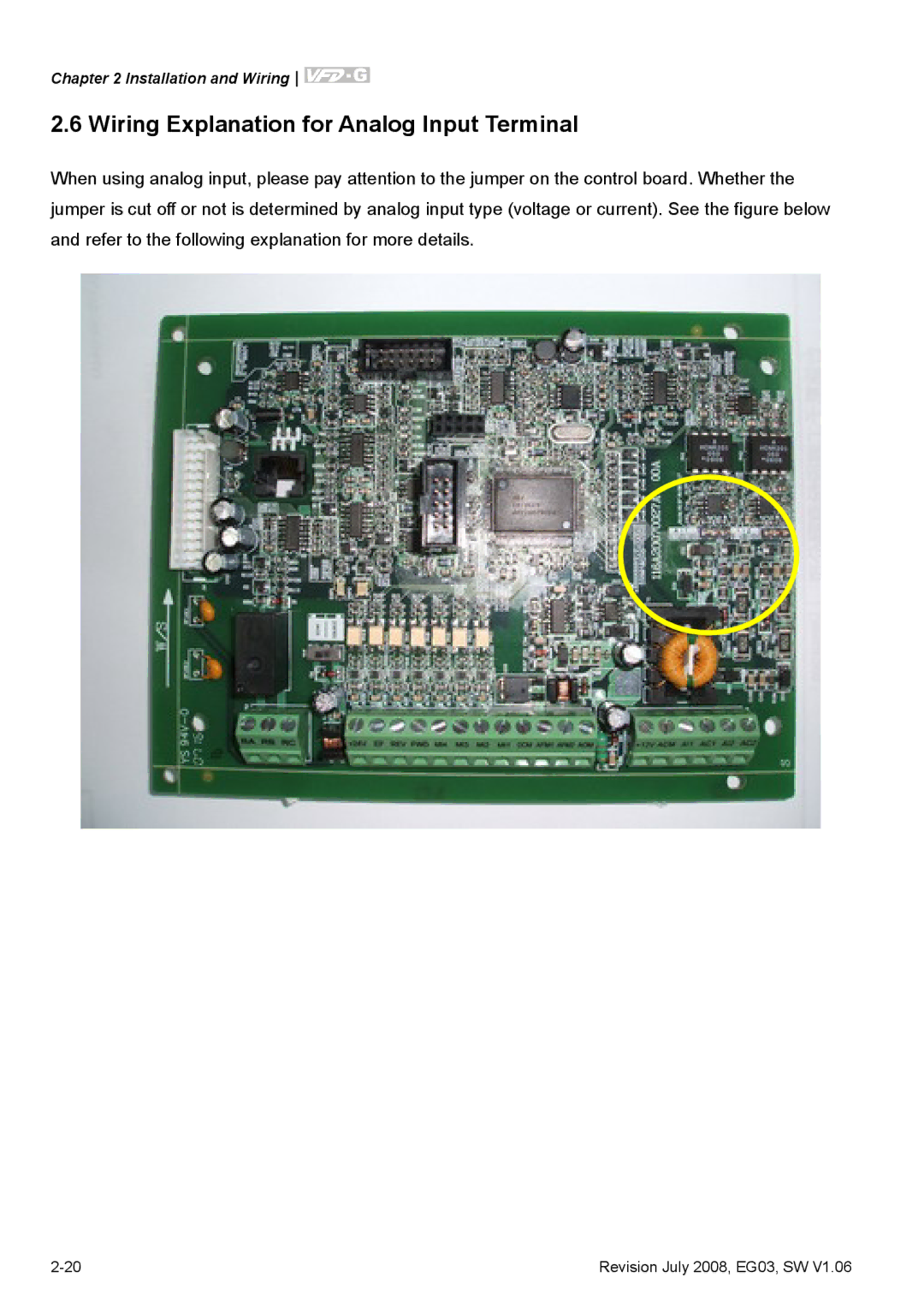
Chapter 2 Installation and Wiring
2-20
1. When using analog current input 0~1A, please plug into the left two pins See the red mark, and make sure the jumper is connected well See what the following yellow arrows point at
Revision July 2008, EG03, SW
Chapter 2 Installation and Wiring
This page intentionally left blank
2-22
3.1 Digital Keypad VFD-PU01 3.1.1 Description of the Digital Keypad
Chapter 3 Keypad and Start Up
STOP RESET
To shift data
3.1.2 How to Operate the Digital Keypad VFD-PU01
Setting direction
START
3.1.4 Reference Table for the LED Display of the Digital Keypad
3.1.3 VFD-PU01 Dimensions
RUN STOP
RESET
3.2 Operation Method
RUN STOP
Check if the motor direction of rotation is correct
3.3 Trial Run
Check if acceleration and deceleration are smooth
Chapter 3 Keypad and Start Up
This page intentionally left blank
Revision July 2008, EG03, SW
Chapter 4 Parameters
Group 0 User Parameters
4.1 Summary of Parameter Settings
Settings
Setting
Functions
Settings
Setting
Parameter
Parameter
Parameter
Functions
Settings
Setting
Parameter
Parameter
Settings
Setting
Group 3 Output Function Parameters
Parameter
Settings
Setting
Group 4 Input Function Parameters
Functions
Settings
Setting
Parameter
Parameter
Settings
Setting
Group 5 Multi-step Speed Parameters
Parameter
Functions
Settings
Setting
Parameter
Parameter
Parameter
Parameter
Functions
Settings
Setting
Parameter
Parameter
Settings
Setting
Group 10 PID Control Parameters
4.2 Parameter Settings for Applications
VFD-G
VFD-G
Emergency Stop by DC Brake
Output Signal during Running
Output Signal for Base Block
This parameter can be set during operation
4.3 Description of Parameter Settings
Code
Bit 8 Master frequency source via communication interface
00 - 14 PLC Time
Group 1 Basic Parameters
01 - 04 Mid-point Voltage
Output Frequency
Output voltage 01-02
01-04
01-06
JOG Frequency
0.1 Sec
01-23
Accel/Decel time unit
1 Sec
Group 2 Operation Method Parameters
15~30HP 3000~6000Hz
Settings
PWM Carrier Frequency Selections
7.5~10HP 4000~6000Hz
RUN/STOP
VFD-G
FWD/STOP
REV/STOP
02 - 07 Reserved
User Defined Coefficient
Descriptions
Setting
Group 3 Output Function Parameters
Functions
Functions
Setting
Frequency 2Hz
Time
03 - 04 DC Fan Control
01 4~20mA
03 - 09 Analog Output 2 Selection Factory Setting
Settings
00 0~20mA
Descriptions
Setting
Group 4 Input Function Parameters
Functions
Functions
Setting
Descriptions
Minimum AI2 Analog Input
Page
1st Analog Input Frequency Gain
Group 5 Multi-step Speed Parameters
05 - 15 PLC Mode
Example 2 Pr.05-15 = 2 Continuously executes program cycles
settings are
Example 3 Pr.05-15 = 3 Execute one cycle step by step
0 0 1 1 1
Weights 0=Forward 1=Reverse
Chapter 4 Parameters
Bit 0 1 0 0 1 1
Time Duration of 1st Step Speed
Chapter 4 Parameters
Frequency
9 1011 12
Multi-Step Speed via External Terminals
Over-current Stall Prevention during Acceleration
Settings
Factory Setting 150%
Time
Over-current Stall Prevention during Operation
Over-current Stall Prevention during Acceleration
06 - 03 Over-torque Detection Selection
Load
80 100 120 140 160
Operation
5 Timemin
Settings
42 CC,OC hardware error HPF2 43 OC hardware error HPF3
Group 7 AC Drive and Motor Parameters
No-load Current of Motor
Rated Slip Frequency of Motor
This parameter could display running time of the motor
Group 8 Special Parameters
DC Braking Time
Momentary Power Loss Operation
08-07 output current
V/f curve setting
Output frequency
Output voltage
Auto Restart Time after Fault
02 AVR function disabled for deceleration
Settings
00 AVR function enabled
01 AVR function disabled
Unit
Settings
Factory Setting
Vibration Compensation Factor
Group 9 Communication Parameters
09 - 05 Even/Odd Parity and Stopping Parity Setting Factory Setting
1 EV 2 GND 3 SG- 4 SG+ 5 NC 6 1 6 for communication
Character ASCII Code Character ASCII Code
RTU mode
ASCII mode
ASCII mode
ASCII mode
RTU mode
ASCII mode
RTU mode
ASCII mode
RTU mode Command message
ASCII mode
RTU mode
RTU mode
Command message ADR CMD Data starting address Number of data word
3.5 Address list
Content
Content
RTU mode
ASCII mode
The explanation of exception codes
Page
Proportional Gain P
Primary Low Pass Filter Time
0 20 40 60 80
V/F Curve Diagram
01-02 Voltage%
Frequency
Revision July 2008, EG03, SW
This page intentionally left blank
Chapter 4 Parameters
4-90
Ov er-curre nt dur ing ac celeratio n
Chapter 5 Troubleshooting
5.1 Over Current OC
o cd
Remove ground fault
5.2 Ground Fault
5.3 Over Voltage OV
Ground fault
Restart after reset
5.4 Low Voltage Lv
Is input power correct? Or power cut, Yes
including momentary power loss
Chapter 5 Troubleshooting
5.5 Over Heat OH
5.6 Overload
Reduce load or increase the power of AC motor drive
Fix connector and eliminate noise No
5.8 Phase Loss PHL
5.7 Keypad Display is Abnormal
Abnormal display or no display Yes Cycle power to AC motor drive
Chapter 5 Troubleshooting
5.9 Motor cannot Run
Revision July 2008, EG03, SW
out of range upper/lower
5.10 Motor Speed cannot be Changed
Chapter 5 Troubleshooting
Check to see if frequency is
settings
5.11 Motor Stalls during Acceleration
5.12 The Motor does not Run as Expected
Chapter 5 Troubleshooting
5.14 Environmental Condition
5.13 Electromagnetic/Induction Noise
serial reactor phase lead capacitor
5.15 Affecting Other Machines
6.1 Fault Code Information
Chapter 6 Fault Code Information and Maintenance
6.1.1 Common Problems and Solutions
Corrective Actions
Fault
Fault Descriptions
Chapter 6 Fault Code Information and Maintenance
Name
Fault
Fault Descriptions
Corrective Actions
Name
Fault
Fault Descriptions
Corrective Actions
Periodic Inspection
6.1.2 Reset
6.2 Maintenance and Inspections
Daily Inspection
DANGER
Periodical Maintenance Ambient environment
Maintenance
Maintenance
Keypad
Terminals and wiring of main circuit
Transformer and reactor of main circuit
Check Items
Maintenance
Maintenance
Cooling fan of cooling system
General Specifications
Appendix A Specifications
General Specifications
Appendix A Specifications
Environment
B.1 All Brake Resistors & Brake Units Used in AC Motor Drives
Appendix B Accessories
9. Definition for Brake Usage ED%
VFD Series
Appendix B Accessories
B.2 Non-fuse Circuit Breaker Chart
B.3 Fuse Specification Chart
B.4.1 AC Input Reactor Recommended Value 460V, 50/60Hz, 3-Phase
B.4 AC Reactor
460V DC Choke
460V, 50/60Hz, 3-Phase
B.4.2 AC Output Reactor Recommended Value
Correct wiring
B.4.3 Applications
Switching spikes will be generated when the
connected to the same power
AC motor drive
power
large-capacity
small-capacity
Diagram A
B.5 Zero Phase Reactor RF220X00A
Diagram B
STOP
B.6 PU06 B.6.1 Description of the Digital Keypad VFD-PU06
B.6.2 Explanation of Display Message
RESET
XXXXX -ERR- -END
B.6.3 PU06 Operation Flow Chart
VFD-PU06 Operation Flow Chart
XX-XX
Related Specification
Appendix C How to Select the Right AC Motor Drive
1.5 the rated current of AC motor drive A
C.1 Capacity Formulas
n T I M ⎢
k ⋅ IM ≤ the rated current of AC motor drive A
Symbol explanation
Parameter Settings Note
C.2 General Precaution
Selection Note
continuous
C.3 How to Choose a Suitable Motor
torque%
25% 40% 60% 100
Special motors
To avoid resonances, use the Skip frequencies
Base freq. 60Hz
60 seconds
torque
Frequency Hz
This page intentionally left blank
Appendix C How to Select the Right AC Motor Drive
Revision July 2008, EG03, SW