Chapter 4 Parameters
When
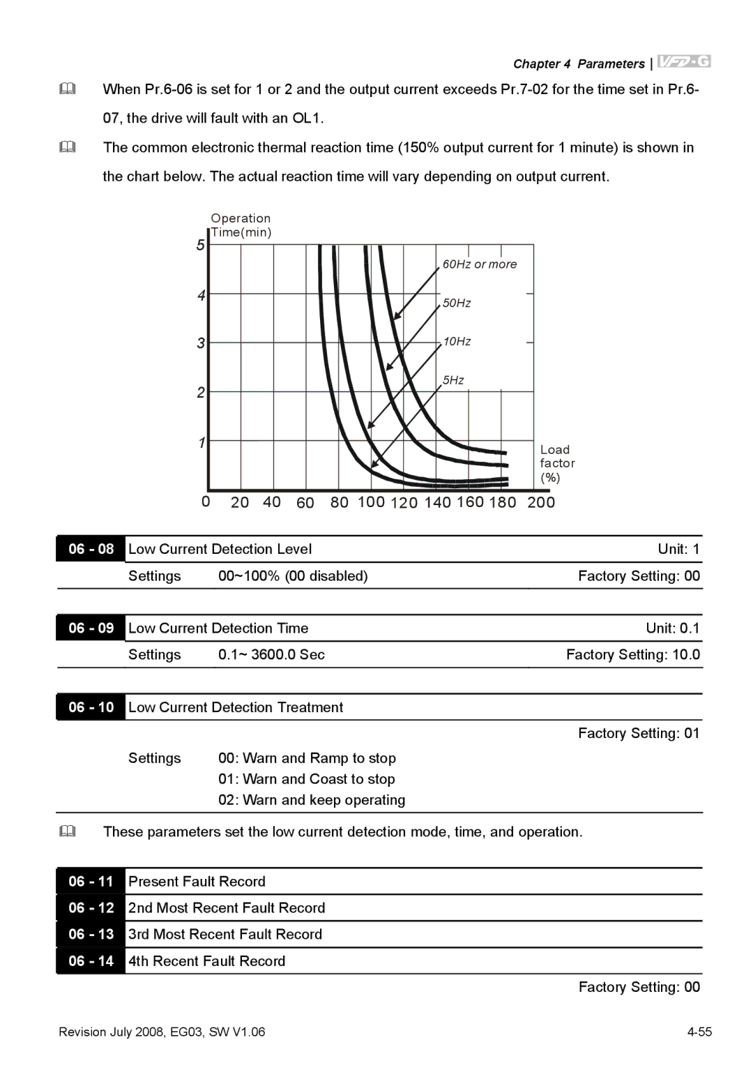
The common electronic thermal reaction time (150% output current for 1 minute) is shown in the chart below. The actual reaction time will vary depending on output current.
| Operation |
|
|
| |
5 Time(min) |
|
|
| ||
|
|
|
| 60Hz or more |
|
4 |
|
|
| 50Hz |
|
|
|
|
|
| |
3 |
|
|
| 10Hz |
|
2 |
|
|
| 5Hz |
|
|
|
|
|
| |
1 |
|
|
|
| Load |
|
|
|
|
| factor |
|
|
|
|
| (%) |
0 | 20 | 40 | 60 | 80 100 120 140 160 180 | 200 |
06 - 08 | Low Current Detection Level | Unit: 1 | |
| Settings | 00~100% (00 disabled) | Factory Setting: 00 |
|
|
| |
|
|
| |
06 - 09 | Low Current Detection Time | Unit: 0.1 | |
| Settings | 0.1~ 3600.0 Sec | Factory Setting: 10.0 |
|
|
| |
|
|
| |
06 - 10 | Low Current Detection Treatment |
| |
|
|
| Factory Setting: 01 |
| Settings | 00: Warn and Ramp to stop |
|
01:Warn and Coast to stop
02:Warn and keep operating
These parameters set the low current detection mode, time, and operation.
06 - 11
06 - 12
06 - 13
06 - 14
Present Fault Record
2nd Most Recent Fault Record
3rd Most Recent Fault Record
4th Recent Fault Record
Factory Setting: 00
Revision July 2008, EG03, SW V1.06 |
