|
|
| Chapter 4 Parameters |
|
|
|
|
|
|
| |
This parameter can be set by communication settings. It can’t be set by keypad. | |||||
|
|
|
| ||
09 - 07 | Communication Frequency Setting | Unit: 0.01 |
| ||
| Settings | 0~160.00Hz | Factory Setting: 60.00 | ||
|
|
| |||
This parameter can be set by communication settings. It can’t be set by keypad. | |||||
|
|
|
|
| |
09 - 08 | Communication Operation Command 2 |
|
|
| |
|
|
| Factory Setting: 00 | ||
| Settings | Bit0: 1: EF ON |
|
|
|
|
| Bit1: 1: Reset |
|
|
|
Bit2: 0: BB OFF, 1: BB ON
Bit3~15: Reserved
This parameter can be set by communication settings. It can’t be set by keypad.
If you set BB action by this parameter and you also need to disable BB action by this parameter.
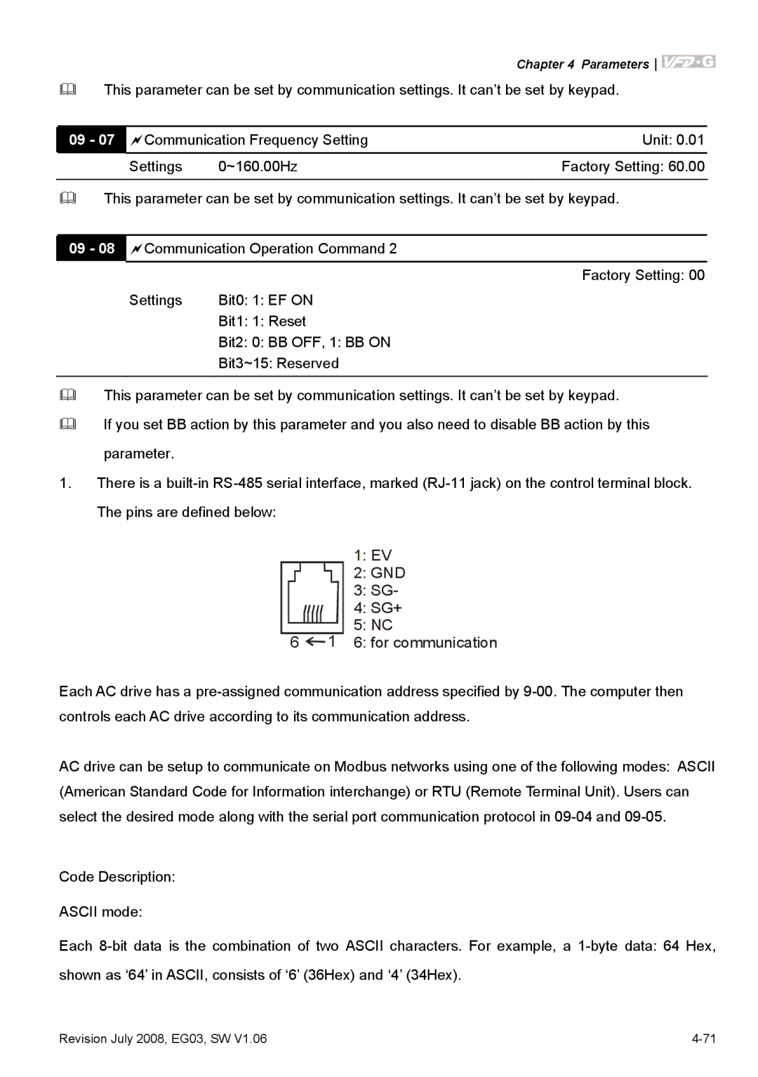
1.There is a
1: EV
2: GND 3: SG- 4: SG+
5: NC
6  1 6: for communication
Each AC drive has a
AC drive can be setup to communicate on Modbus networks using one of the following modes: ASCII (American Standard Code for Information interchange) or RTU (Remote Terminal Unit). Users can select the desired mode along with the serial port communication protocol in
Code Description:
ASCII mode:
Each
Revision July 2008, EG03, SW V1.06 |