Appendix B Accessories
NFB | MC |
|
|
|
| |
R/L1 | U/T1 |
|
|
| ||
R/L1 |
|
|
| |||
S/L2 | S/L2 | V/T2 |
| IM |
| |
T/L3 | T/L3 | W/T3 |
| MOTOR | Thermal Overload | |
| VFD Series |
|
| |||
O.L. | +(P) | B1 | Relay | |||
Thermal | MC | +(P) | O.L. | |||
| ||||||
|
| Brake | ||||
Overload | SA | Brake | ||||
E.F | RA | BR Resistor | ||||
Relay or | Surge | |||||
temperature | Absorber | DCM | RC | Unit |
| |
B2 | Temperature | |||||
switch |
|
|
| |||
|
|
|
|
| Switch | |
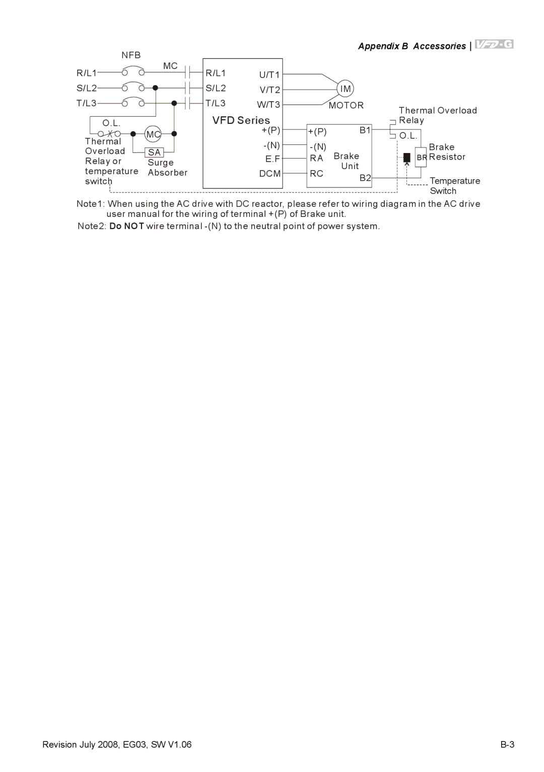
Note1: When using the AC drive with DC reactor, please refer to wiring diagram in the AC drive user manual for the wiring of terminal +(P) of Brake unit.
Note2: Do NOT wire terminal
Revision July 2008, EG03, SW V1.06 |