|
|
| Chapter 4 Parameters |
|
|
| |
|
|
|
|
|
| ||
|
|
|
|
|
|
| |
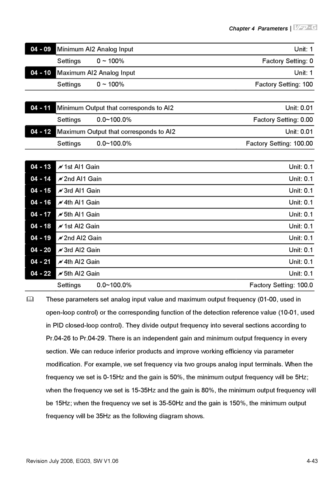
04 - 09 | Minimum AI2 Analog Input |
|
| Unit: 1 |
| ||
| Settings | 0 ~ 100% |
| Factory Setting: 0 | |||
|
|
|
|
|
| ||
04 - 10 | Maximum AI2 Analog Input |
|
| Unit: 1 | |||
| Settings | 0 ~ 100% |
| Factory Setting: 100 |
| ||
|
|
|
| ||||
04 - 11 | Minimum Output that corresponds to AI2 |
| Unit: 0.01 |
| |||
| Settings | 0.0~100.0% |
| Factory Setting: 0.00 | |||
|
|
|
| ||||
04 - 12 | Maximum Output that corresponds to AI2 |
| Unit: 0.01 |
| |||
| Settings | 0.0~100.0% |
| Factory Setting: 100.00 | |||
|
|
|
|
| |||
|
|
|
|
| |||
04 - 13 | 1st AI1 Gain |
| Unit: 0.1 |
| |||
04 - 14 | 2nd AI1 Gain |
| Unit: 0.1 |
| |||
04 - 15 | 3rd AI1 Gain |
| Unit: 0.1 |
| |||
04 - 16 | 4th AI1 Gain |
| Unit: 0.1 |
| |||
04 - 17 | 5th AI1 Gain |
| Unit: 0.1 |
| |||
04 - 18 | 1st AI2 Gain |
| Unit: 0.1 |
| |||
04 - 19 | 2nd AI2 Gain |
| Unit: 0.1 |
| |||
04 - 20 | 3rd AI2 Gain |
| Unit: 0.1 | ||||
04 - 21 | 4th AI2 Gain |
| Unit: 0.1 | ||||
04 - 22 | 5th AI2 Gain |
| Unit: 0.1 | ||||
| Settings | 0.0~100.0% |
| Factory Setting: 100.0 | |||
|
|
|
|
|
|
|
|
These parameters set analog input value and maximum output frequency
Revision July 2008, EG03, SW V1.06 |
