Chapter 2 Installation and Wiring![]()
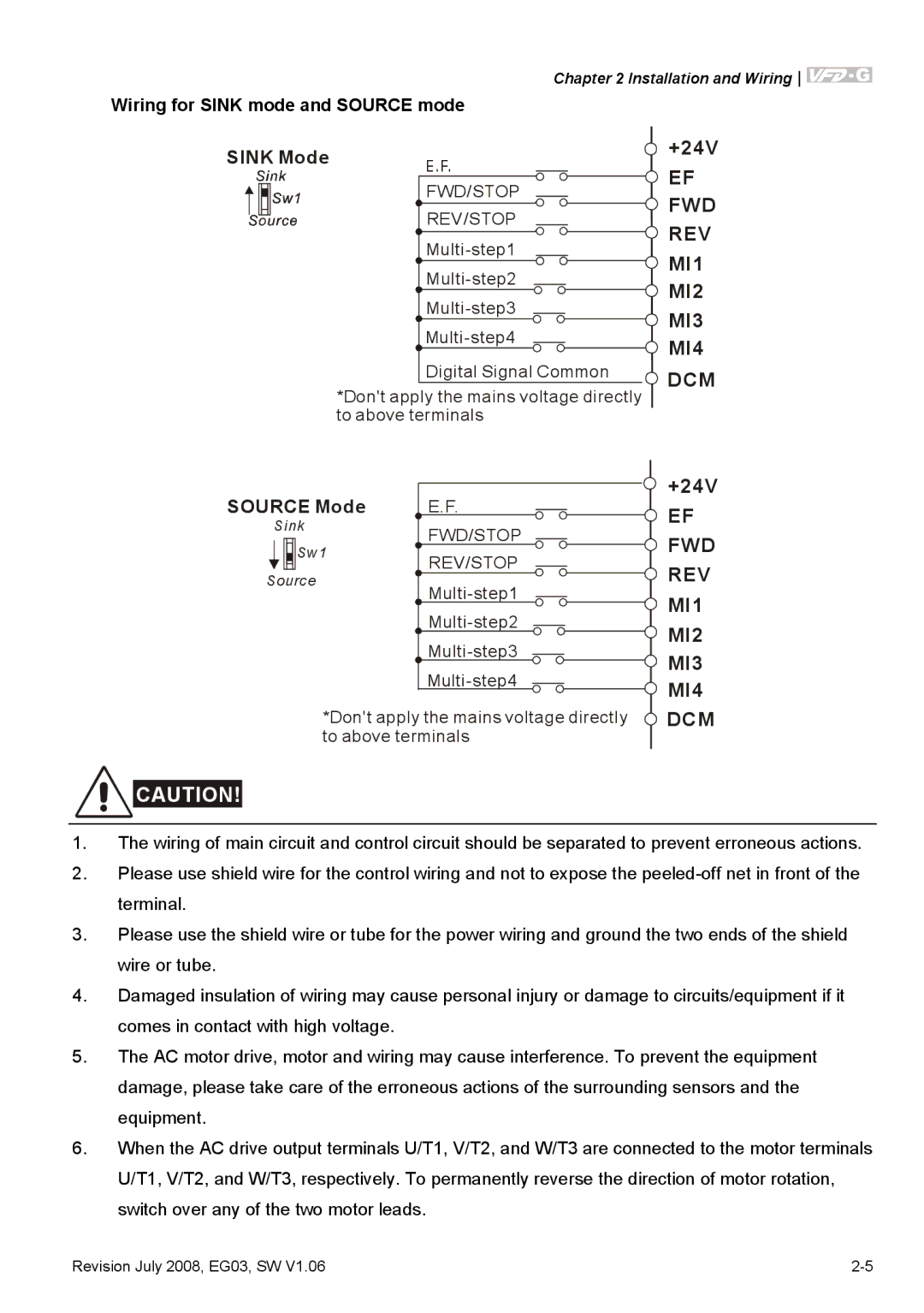
Wiring for SINK mode and SOURCE mode
SINK Mode | E.F. |
| |
| FWD/STOP |
| REV/STOP |
| |
| |
| |
| |
| Digital Signal Common |
*Don't apply the mains voltage directly to above terminals
SOURCE Mode | E.F. | |
Sink | FWD/STOP | |
Sw1 | ||
REV/STOP | ||
Source | ||
| ||
| ||
| ||
|
*Don't apply the mains voltage directly to above terminals
![]() CAUTION!
CAUTION!
+24V
![]() EF
EF
![]() FWD
FWD
![]() REV
REV
![]() MI1
MI1
![]() MI2
MI2
![]() MI3
MI3
![]() MI4
MI4
![]() DCM
DCM
+24V
![]() EF
EF
![]() FWD
FWD
![]() REV
REV
![]() MI1
MI1
![]() MI2
MI2
![]() MI3
MI3
![]() MI4
MI4
![]() DCM
DCM
1.The wiring of main circuit and control circuit should be separated to prevent erroneous actions.
2.Please use shield wire for the control wiring and not to expose the
3.Please use the shield wire or tube for the power wiring and ground the two ends of the shield wire or tube.
4.Damaged insulation of wiring may cause personal injury or damage to circuits/equipment if it comes in contact with high voltage.
5.The AC motor drive, motor and wiring may cause interference. To prevent the equipment damage, please take care of the erroneous actions of the surrounding sensors and the equipment.
6.When the AC drive output terminals U/T1, V/T2, and W/T3 are connected to the motor terminals U/T1, V/T2, and W/T3, respectively. To permanently reverse the direction of motor rotation, switch over any of the two motor leads.
Revision July 2008, EG03, SW V1.06 |