PC1
kS
nT nS
GD2
TL tA
cosϕ
VM
IM
Appendix C How to Select the Right AC Motor Drive![]()
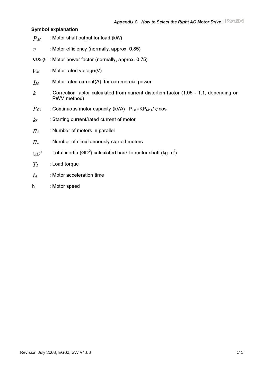
Symbol explanation
PM | : Motor shaft output for load (kW) |
η: Motor efficiency (normally, approx. 0.85)
: Motor power factor (normally, approx. 0.75)
: Motor rated voltage(V)
: Motor rated current(A), for commercial power
k: Correction factor calculated from current distortion factor (1.05 - 1.1, depending on PWM method)
: Continuous motor capacity (kVA) PC1=KPMnT/ηcos
: Starting current/rated current of motor
: Number of motors in parallel
: Number of simultaneously started motors
: Total inertia (GD2) calculated back to motor shaft (kg m2)
: Load torque
: Motor acceleration time
N : Motor speed
Revision July 2008, EG03, SW V1.06 |
