Page
Page
Page
Preface
Page
Table of Contents
Keypad and Start Up
Troubleshooting
Parameters
Fault Code Information and Maintenance
Appendix a Specifications Appendix B Accessories
Appendix C How to Select the Right AC Motor Drive
Nameplate Information
Receiving and Inspection
Model Explanation
Appearances
Series Number Explanation
Drive Frames
20HP/5.5-15kWFrame C 25-40HP/18.5-30kWFrame D
Introduction
Remove Instructions 1.3.1 Remove Keypad
Remove Front Cover
Introduction
Lifting
Step
For 250-300HP Frame H
Operation
Preparation for Installation and Wiring Ambient Conditions
Minimum Mounting Clearances
Storage
Introduction
Dimensions
Frame
425.016.73 381.015.00 850.033.46 819.532.26
This page intentionally left blank
Installation and Wiring
Wiring
VFD-G
For 460V series, 25hp and above
Sink Mode
Wiring for Sink mode and Source mode
Excellent Good Not allowed
External Wiring
FUSE/NFB
Main Circuit Connection
Terminal Symbol
Explanation of Terminal Function
Terminals +1, +2+2/B1 for connecting DC reactor
Mains power terminals R/L1, S/L2, T/L3
Output terminals for main circuit U, V, W
Vfdb
Control Terminals
MI4
Analog inputs AI1, AI2, AC1, AC2
Relay outputs RA1, RB1, RC1
General
Power Motor
HP to 40 HP VFD185F43A-G, VFD220F43A-G, VFD300F43A-G
HP to 60 HP VFD370F43A-G, VFD450F43A-G
HP to 125 HP VFD550F43A-G, VFD750F43A-G, VFD900F43C-G
HP to 215 HP VFD1100F43C-G, VFD1320F43A-G, VFD1600F43A-G
HP to 300 HP VFD1850F43A-G, VFD2200F43A-G
Wiring Explanation for Analog Input Terminal
Installation and Wiring
This page intentionally left blank
Display Message
Digital Keypad VFD-PU01 Description of the Digital Keypad
Descriptions
How to Operate the Digital Keypad VFD-PU01
Display Message Descriptions
VFD-PU01 Dimensions
Reference Table for the LED Display of the Digital Keypad
RUN Stop
Operation Method
Trial Run
This page intentionally left blank
Parameters
Summary of Parameter Settings
Group 0 User Parameters Functions Settings Factory Customer
Parameter Functions Settings Factory Customer
Setting
Parameter Functions Settings Factory
Group 1 Basic Parameters Functions Settings Factory
= coast to stop
Parameter Functions Settings Factory
Parameters
Parameters
04-24 Analog Input Delay 00~10.00 Sec
Execute one program cycle step by step
Time Duration Step To 65500 Sec / 0.0~6550.0 Sec
Parameter Functions Settings Factory
Parameter Functions Settings Factory Customer
Setting
Parameter Functions Settings Factory Customer
Parameter Functions Settings Factory Customer
Parameters
DC Brake before Running Applications Purpose Functions
Parameter Settings for Applications
Multi-step Operation Applications Purpose Functions
Auto Restart after Fault Applications Purpose
Two-wire/three-wire Applications Purpose
Operation Command Applications Purpose
Frequency Hold Applications Purpose
Parameters
Parameters
Multi-function Analog Output Applications Purpose Functions
Description of Parameter Settings
Group 0 User Parameters
Fanp
Parameters
00 14 PLC Time
Group 1 Basic Parameters
01 04 Mid-point Voltage Settings 2V~510.0V
Parameters
Unit 0.1sec
Parameters
Group 2 Operation Method Parameters
PWM Carrier Frequency Selections Settings ~10HP 4000~6000Hz
VFD-G
02 07 Reserved
Flying Start Factory Setting
Setting Functions Descriptions
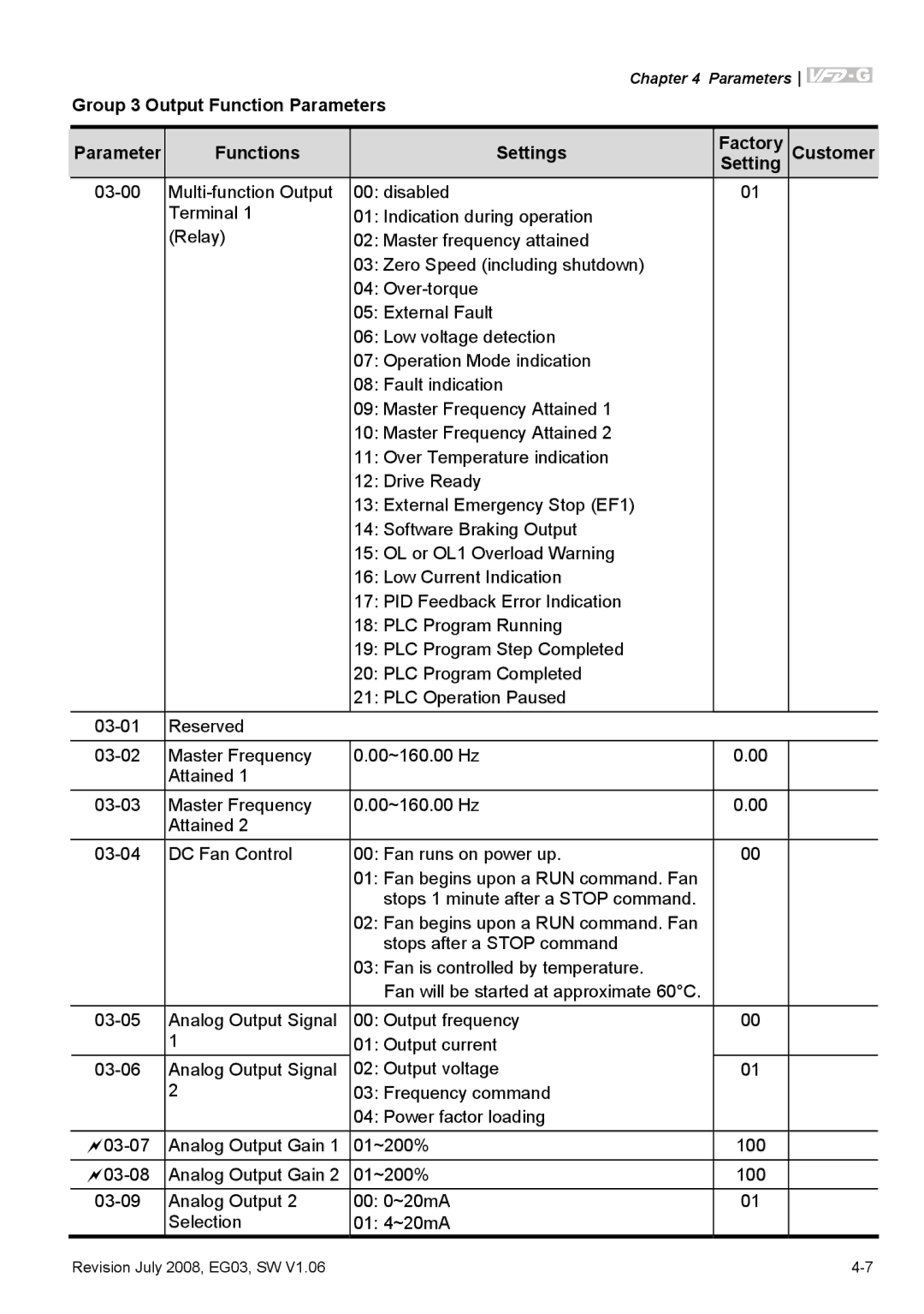
Group 3 Output Function Parameters
Frequency 2Hz
03 04 DC Fan Control
Parameters
Group 4 Input Function Parameters
Setting Functions Descriptions
Parameters
Max AI1*AI1 Gain, AI2*AI2 Gain
Factory Setting
05 15 PLC Mode
Group 5 Multi-step Speed Parameters
Example 2 Pr.05-15 = 2 Continuously executes program cycles
Example 3 Pr.05-15 = 3 Execute one cycle step by step
Bit 0 1 0 0 1 1 1 1 1
Parameters
Frequency
Time
Group 6 Protection Function Parameters
06-01
06 03 Over-torque Detection Selection
80 100 120 140 160 200
Parameters
Delta
Group 7 AC Drive and Motor Parameters
18.5 110 132 160 185 220
Parameters
Parameters
Accumulated Electric Bill per currency unit
Group 8 Special Parameters
DC Braking Time
Momentary Power Loss Operation
Output frequency
Parameters
100% 70%
Parameters
Group 9 Communication Parameters
None parity + 2 stop bit
GND 3 SG- 4 SG+ 6 for communication
Start Stop Stop
Ascii mode
RTU mode
Command message Response message Error response message
CDH
C6H
RTU mode Command message
High
0FH
‘0’ ‘1’
ADR CMD
BB OFF
Content Address Function
Rev LED is on and FWD led is off. Reverse
LRC CHK
Communication time-out
Group 10 PID Control Parameters
Parameters
Determined by group
Curve Diagram
This page intentionally left blank
Troubleshooting
Over Current OC
Ground Fault
Over Voltage OV
Low Voltage Lv
Over Heat OH
Overload
Phase Loss PHL
Keypad Display is Abnormal
Motor cannot Run
Motor Speed cannot be Changed
Motor Stalls during Acceleration
Motor does not Run as Expected
Electromagnetic/Induction Noise
Environmental Condition
Serial reactor Phase lead capacitor
Affecting Other Machines
Common Problems and Solutions
Fault Code Information
Fault Fault Descriptions Corrective Actions Name
Ensure that the ambient temperature falls within
Fault Fault Descriptions Corrective Actions Name
Fault Fault Descriptions Corrective Actions Name
Daily Inspection
Reset
Maintenance and Inspections
Periodic Inspection
Voltage Maintenance Check Items Methods and Criterion
Main circuit Maintenance Check Items Methods and Criterion
Keypad Maintenance Check Items Methods and Criterion
Change of copper plate
One
One Year
Daily
Appendix a Specifications
Appendix a Specifications
Appendix B Accessories
All Brake Resistors & Brake Units Used in AC Motor Drives
Appendix B Accessories
VFD Series
Non-fuse Circuit Breaker Chart
Fuse Specification Chart
AC Reactor
AC Input Reactor Recommended Value 460V, 50/60Hz, 3-Phase
460V DC Choke
460V, 50/60Hz, 3-Phase
AC Output Reactor Recommended Value
Correct wiring
Applications
Reduce harmonics and provide protection from
Diagram a
Zero Phase Reactor RF220X00A
Diagram B
PU06 Description of the Digital Keypad VFD-PU06
Explanation of Display Message
3 PU06 Operation Flow Chart
XX-XX
Appendix C How to Select the Right AC Motor Drive
Related Specification
When one AC motor drive operates more than one motor
When one AC motor drive operates one motor
Capacity Formulas
Symbol explanation
Parameter Settings Note
General Precaution
Selection Note
How to Choose a Suitable Motor
Standard motor
Special motors
Pole-changing Dahlander motor
Power Transmission Mechanism
Motor torque
This page intentionally left blank