Chapter 2 Installation and Wiring
7.With long motor cables, high capacitive switching current peaks can cause over-current, high leakage current or lower current readout accuracy. To prevent this, the motor cable should be less than 20m for 3.7kW models and below. And the cable should be less than 50m for 5.5kW models and above. For longer motor cables use an AC output reactor.
8.The AC motor drive, electric welding machine and the greater horsepower motor should be grounded separately.
9.Use ground leads that comply with local regulations and keep them as short as possible.
10.No brake resistor is built in the VFD-G series, it can install brake resistor for those occasions that use higher load inertia or frequent start/stop. Refer to Appendix B for details.
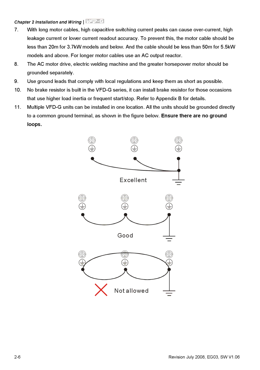
11.Multiple VFD-G units can be installed in one location. All the units should be grounded directly to a common ground terminal, as shown in the figure below. Ensure there are no ground loops.
Excellent
Good
Not allowed
2-6 | Revision July 2008, EG03, SW V1.06 |