| LSI Specification |
|
|
|
|
|
|
|
|
|
| MB86617A | ||||||||
| 10.1. |
|
|
|
|
|
| |||||||||||||
|
|
|
|
|
|
|
|
|
|
|
|
|
|
|
|
|
|
|
| |
| AD | R/ョ | Bit | Bit | Bit | Bit | Bit | Bit | Bit | Bit | Bit | Bit | Bit |
| Bit | Bit | Bit | Bit | Bit | |
| 15 | 14 | 13 | 12 | 11 | 10 | 9 | 8 | 7 | 6 | 5 |
| 4 | 3 | 2 | 1 | 0 |
| ||
|
|
|
|
| ||||||||||||||||
|
|
|
|
|
|
|
|
|
|
|
|
|
|
|
|
|
|
|
| |
|
| R | INT | INT | INT | INT | INT | INT | INT | INT | INT | INT | INT |
| INT | INT | INT | INT | INT | |
|
| 1 | 2 | 3 | 4 | 5 | 6 | 7 | 8 | 9 | 10 | 11 |
| 12 | 13 | 14 | 15 | 16 | ||
| 06h |
|
| |||||||||||||||||
|
|
|
|
|
|
|
|
|
|
|
|
|
|
|
|
|
|
|
| |
| W |
|
|
|
|
|
|
|
|
|
|
|
|
|
|
|
| |||
|
|
|
|
|
|
|
|
|
|
|
|
|
|
|
|
|
| |||
|
|
|
|
|
|
|
|
|
|
|
|
|
|
|
|
|
|
| ||
|
| R | INT | INT | INT | INT | INT | INT | INT | INT | INT | INT | INT |
| INT | INT | INT | INT | INT | |
|
| 17 | 18 | 19 | 20 | 21 | 22 | 23 | 24 | 25 | 26 | 27 |
| 28 | 29 | 30 | 31 | 32 | ||
| 08h |
|
| |||||||||||||||||
|
|
|
|
|
|
|
|
|
|
|
|
|
|
|
|
|
|
|
| |
| W |
|
|
|
|
|
|
|
|
|
|
|
|
|
|
|
| |||
|
|
|
|
|
|
|
|
|
|
|
|
|
|
|
|
|
| |||
|
|
|
|
|
|
|
|
|
|
|
|
|
|
|
|
|
|
| ||
| Intial Value | ‘0’ | ‘0’ | ‘0’ | ‘0’ | ‘0’ | ‘0’ | ‘0’ | ‘0’ | ‘0’ | ‘0’ | ‘0’ |
| ‘0’ | ‘0’ | ‘0’ | ‘0’ | ‘0’ | ||
|
|
|
|
|
|
|
|
|
|
|
|
|
|
|
|
|
|
|
|
|
>
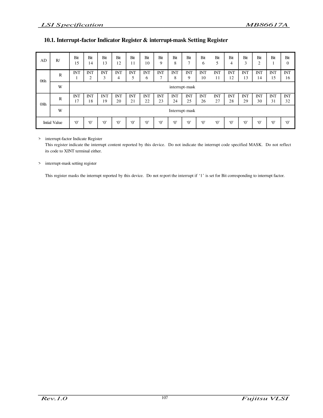
This register indicate the interrupt content reported by this device. Do not indicate the interrupt code specified MASK. Do not reflect its code to XINT terminal either.
>
This register masks the interrupt reported by this device. Do not report the interrupt if ‘1’ is set for Bit corresponding to interrupt factor.
Rev.1.0 | 107 | Fujitsu VLSI |
