LSI Specification | MB86617A |
5.5. Other Pins
This section explains the pin function like internal PLL.
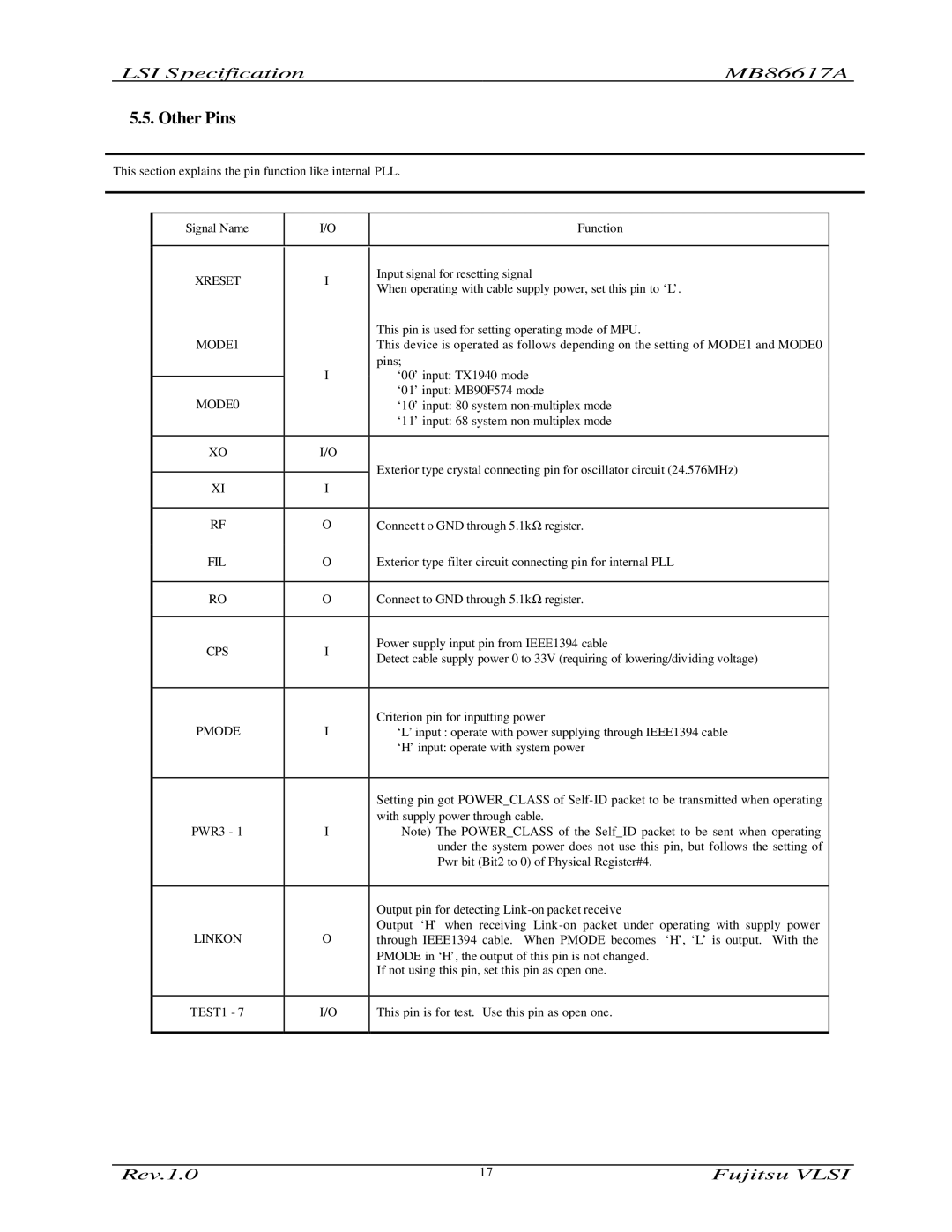
Signal Name | I/O | Function | |
|
|
| |
XRESET | I | Input signal for resetting signal | |
When operating with cable supply power, set this pin to ‘L’. | |||
|
| ||
|
| This pin is used for setting operating mode of MPU. | |
MODE1 |
| This device is operated as follows depending on the setting of MODE1 and MODE0 | |
|
| pins; | |
| I | ‘00’ input: TX1940 mode | |
| |||
MODE0 |
| ‘01’ input: MB90F574 mode | |
| ‘10’ input: 80 system | ||
|
| ‘11’ input: 68 system | |
|
|
| |
XO | I/O |
| |
|
| Exterior type crystal connecting pin for oscillator circuit (24.576MHz) | |
XI | I | ||
| |||
|
|
| |
RF | O | Connect t o GND through 5.1kΩ register. | |
FIL | O | Exterior type filter circuit connecting pin for internal PLL | |
|
|
| |
RO | O | Connect to GND through 5.1kΩ register. | |
|
|
| |
CPS | I | Power supply input pin from IEEE1394 cable | |
Detect cable supply power 0 to 33V (requiring of lowering/dividing voltage) | |||
|
| ||
|
|
| |
PMODE | I | Criterion pin for inputting power | |
‘L’ input : operate with power supplying through IEEE1394 cable | |||
|
| ‘H’ input: operate with system power | |
|
|
| |
|
| Setting pin got POWER_CLASS of | |
|
| with supply power through cable. | |
PWR3 - 1 | I | Note) The POWER_CLASS of the Self_ID packet to be sent when operating | |
|
| under the system power does not use this pin, but follows the setting of | |
|
| Pwr bit (Bit2 to 0) of Physical Register#4. | |
|
|
| |
|
| Output pin for detecting | |
LINKON | O | Output ‘H’ when receiving Link | |
through IEEE1394 cable. When PMODE becomes ‘H’, ‘L’ is output. With the | |||
|
| PMODE in ‘H’, the output of this pin is not changed. | |
|
| If not using this pin, set this pin as open one. | |
|
|
| |
TEST1 - 7 | I/O | This pin is for test. Use this pin as open one. | |
|
|
|
Rev.1.0 | 17 | Fujitsu VLSI |