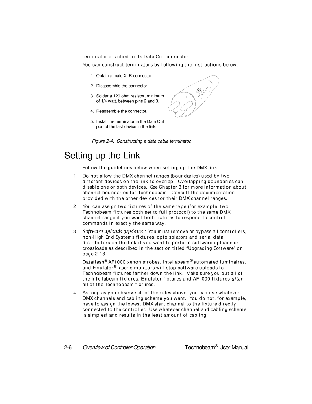
terminator attached to its Data Out connector.
You can construct terminators by following the instructions below:
1.Obtain a male XLR connector.
2.Disassemble the connector.
3.Solder a 120 ohm resistor, minimum of 1/4 watt, between pins 2 and 3.
4.Reassemble the connector.
5.Install the terminator in the Data Out port of the last device in the link.
|
| Ω |
| 0 | |
2 |
| |
1 |
|
|
Figure 2-4. Constructing a data cable terminator.
Setting up the Link
Follow the guidelines below when setting up the DMX link:
1.Do not allow the DMX channel ranges (boundaries) used by two different devices on the link to overlap. Overlapping boundaries can disable one or both devices. See Chapter 3 for more information about channel boundaries for Technobeam. Consult the documentation provided with the other devices for their DMX channel ranges.
2.You can assign two fixtures of the same type (for example, two Technobeam fixtures both set to full protocol) to the same DMX channel range if you want both fixtures to respond to control commands in exactly the same way.
3.Software uploads (updates): You must remove or bypass all controllers,
Dataflash® AF1000 xenon strobes, Intellabeam® automated luminaires, and Emulator® laser simulators will stop software uploads to Technobeam fixtures farther down the link. Make sure you put all of the Intellabeam fixtures, Emulator fixtures and AF1000 fixtures after all of the Technobeam fixtures.
4.As long as you observe all of the rules above, you can use whatever DMX channels and cabling scheme you want. You do not, for example, have to assign the lowest DMX start channel to the fixture directly connected to the controller. Use whatever channel and cabling scheme is simplest and results in the least amount of cabling.
Overview of Controller Operation | Technobeam® User Manual |
