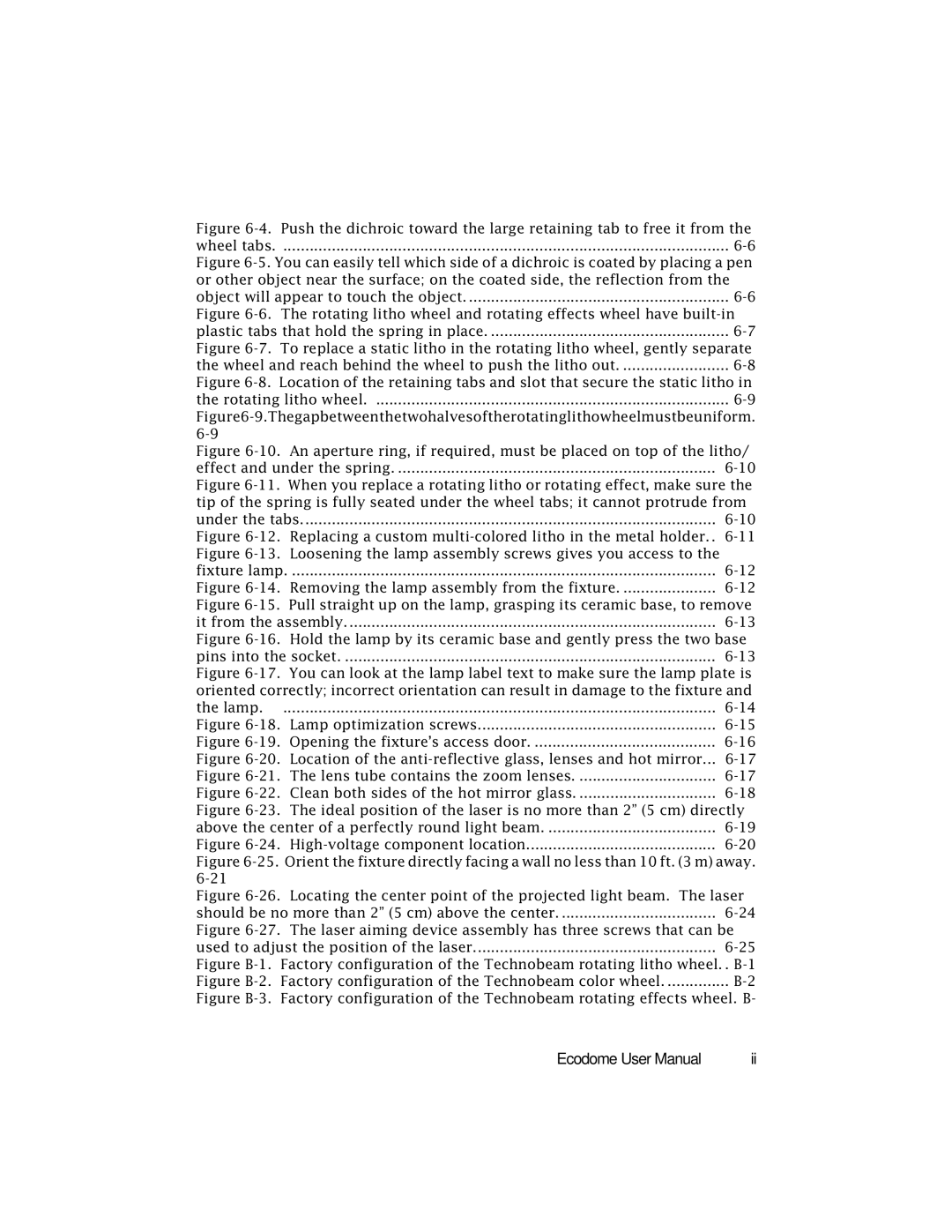
Figure 6-4. Push the dichroic toward the large retaining tab to free it from the
wheel tabs |
Figure 6-5. You can easily tell which side of a dichroic is coated by placing a pen or other object near the surface; on the coated side, the reflection from the
object will appear to touch the object |
Figure 6-6. The rotating litho wheel and rotating effects wheel have built-in
plastic tabs that hold the spring in place |
Figure 6-7. To replace a static litho in the rotating litho wheel, gently separate
the wheel and reach behind the wheel to push the litho out |
Figure 6-8. Location of the retaining tabs and slot that secure the static litho in the rotating litho wheel. ................................................................................ 6-9
Figure6-9.Thegapbetweenthetwohalvesoftherotatinglithowheelmustbeuniform. 6-9
Figure 6-10. An aperture ring, if required, must be placed on top of the litho/
effect and under the spring |
Figure 6-11. When you replace a rotating litho or rotating effect, make sure the tip of the spring is fully seated under the wheel tabs; it cannot protrude from
under the tabs | ||
Figure | Replacing a custom | |
Figure | Loosening the lamp assembly screws gives you access to the |
|
fixture lamp | ||
Figure | Removing the lamp assembly from the fixture | |
Figure | Pull straight up on the lamp, grasping its ceramic base, to remove | |
it from the assembly | ||
Figure 6-16. Hold the lamp by its ceramic base and gently press the two base
pins into the socket |
Figure 6-17. You can look at the lamp label text to make sure the lamp plate is oriented correctly; incorrect orientation can result in damage to the fixture and
the lamp | ||
Figure | Lamp optimization screws | |
Figure | Opening the fixture’s access door | |
Figure | Location of the | |
Figure | The lens tube contains the zoom lenses | |
Figure | Clean both sides of the hot mirror glass | |
Figure | The ideal position of the laser is no more than 2” (5 cm) directly | |
above the center of a perfectly round light beam | ||
Figure |
| |
Figure 6-25. Orient the fixture directly facing a wall no less than 10 ft. (3 m) away. 6-21
Figure 6-26. Locating the center point of the projected light beam. The laser
should be no more than 2” (5 cm) above the center |
Figure 6-27. The laser aiming device assembly has three screws that can be
used to adjust the position of the laser | ||
Figure | Factory configuration of the Technobeam rotating litho wheel. | . |
Figure | Factory configuration of the Technobeam color wheel | |
Figure | Factory configuration of the Technobeam rotating effects wheel. B- | |
Ecodome User Manual | ii |
