HP 53131A/132A 225 MHz Universal Counter
Page
Programming Guide
Certification Warranty
Contents
Remote
Status Reporting
How to Program the Counter to Display Results
Programming Guide Vii
Command Reference
STATus Subsystem
Errors
Before You Start
Introduction
Introduction
Programming Guide Contents
HP 53131A Containing Firmware Revisions 3317, 3335, or
Calibrations
HP-IB Commands
Measurements
Statistics
HP 53132A Time Interval De lay Arming
New Users
How to Use This Guide
Getting Started
What You Should Understand
Experienced Programmers
Learning to Program the Counter
How to Use This Guide
Applications
Programming Guide Contents
Assumptions
Related Documentation
Related Documentation
Programming Guide Contents
Related Documentation
Command Summary
Chapter Summary
Front Panel to Scpi Command Maps
Front Panel to Scpi Command Maps
Some Scpi Syntax Conventions
Input Channels Conditioning Keys to Scpi Command Map
Input Channels Conditioning Keys to Scpi Command Map Part 1
Input Channels Conditioning Keys to Scpi Command Map Part 2
Front Panel to Scpi Command Maps
RCL Nrf
Measure Keys to Scpi Command Map
Measure Keys to Scpi Command Map Part 1
Measure Keys to Scpi Command Map Part 2
Gate & ExtArm Key to Scpi Command Map
Gate & ExtArm Key to Scpi Command Map Part 1
Phase
Freq, Period, Ratio
Totalize
Rise Time, Fall Time, +/- Pulse Width, Dutycycle
Gate & ExtArm Key to Scpi Command Map Part 4
Gate & ExtArm Key to Scpi Command Map Part 5
Gate & ExtArm Key to Scpi Command Map Part 6
Limits and Math Keys to Scpi Command Map
Limits and Math Keys to Scpi Command Map Part 1
Limits and Math Keys to Scpi Command Map Part 2
Calibration Menu to Scpi Command Map
Calibration Menu to Scpi Command Map Part 1
Calibration Menu to Scpi Command Map Part 2
HP 53131A/132A Command Summary
HP 53131A/132A Command Summary
Scpi Conformance Information
Ieee 488.2 Common Commands
HP 53131A/132A Command Summary Ieee 488.2 Common Commands
Mnemonic Command Name Function
Front Panel to Scpi Command Maps Ieee 488.2 Common Commands
RCL
HP 53131A/132A Scpi Subsystem Commands
Std/New Column
Parameter Form Column
Keyword/Syntax Parameter Form Std Comments New ABORt
CALCulate1
CALCulate2
Keyword/Syntax Parameter Form Std Comments New CALCulate2
CALCulate3
Keyword/Syntax Parameter Form Std Comments New CALCulate3
CONFigure
DIAGnostic
CALibration
FETCh
Keyword/Syntax Parameter Form Std Comments New DIAGnostic
DISPlay
FORMat
INPut3
Keyword/Syntax Parameter Form Std Comments New INITiate
INPut12
MEASure
CONFigure?
Function Parameters Sourcelist Std New
Keyword/Syntax Parameter Form Std Comments New MEMory
SENSe
Keyword/Syntax Parameter Form Std Comments New SENSe
ARM
On OFF Once
HP 53132A with 2-38 for HP
ARM commands
ARM HP 53131A See -2A on
Prefix below 53132A with S/N
STATus
Keyword/Syntax Parameter Form Std Comments New SYSTem
TRACe
TRIGger
Estart
Stop
RST Response
Command Header Parameter State
RST Response
HP 53131A /132A *RST State
Front Panel to Scpi Command Maps HP 53131A/132A *RST State
1E6 OHM
3B. HP 53132A S/N 3646 and above Time Interval *RST State
Front Panel to Scpi Command Maps Unaffected by *RST
ESE OPC? SRE
RST Response
Programming Your Universal Counter for Remote Operation
Where to Find Some Specific Information
Where to Find Turbo C Programming Examples
Where to Find HP Basic Programming Examples
Where to Find QuickBASIC Programming Examples
Elements of Scpi Commands
Configuring the HP-IB
To Set the HP-IB Mode and Address
Configuring the HP-IB
HP-IB
To Connect the Counter to a Computer
Remote/Local Operation
Overview of Command Types and Formats
Common Command Format
Scpi Command and Query Format
Elements of Scpi Commands
Subsystem Command Syntax
Common Command Syntax
Abbreviated Commands
Keyword Separator
Optional Keyword
Implied Channel Optional Numeric Keyword Suffix
ARM Stop
Command and Query Parameter Types
Parameter Types
Suffixes
Parameter Separator
Query Parameters
Suffix Elements
Command Terminator
Suffix Multipliers
Suffix Multipliers
Program Messages
Using Multiple Commands
Using Multiple Commands
Program Message Syntax
Inpcoup AC Inpimp Inpcoup Acinpimp
Response Message Syntax
Overview of Response Message Formats
Response Messages
Overview of Response Message Formats
Response Message Data Types
Response Message Data Types
Type Description
Overview of Response Message Formats
Status Reporting
Status Reporting
Status Byte Register and Service Request Enable Register
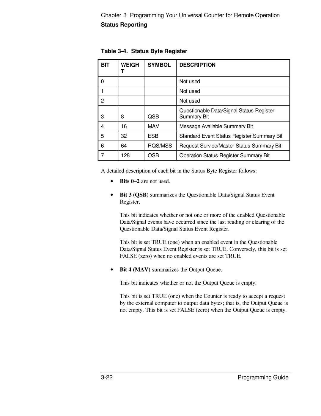
Status Byte Register
BIT Weigh Symbol Description
Status Reporting Status Byte Register
Service Request Enable Register
Standard Event Status Register Group
Standard Event Status Register
Standard Event Status Register
Elements of Scpi Commands
Standard Event Status Enable Register
Operation and Questionable Status Reporting Model
Condition Register
Transition Filter
Transition Filter Definition
Event Enable Register
Event Register
Operation Status Register Group
Operation Status Register
Elements of Scpi Commands
Questionable Data/Signal Status Register Group
Questionable Data/Signal Status Register
Elements of Scpi Commands
Status Reporting
Command Settings for Optimizing Throughput
Commands to Set Counter for Optimal Throughput
Command Settings for Optimizing Throughput
SENSeROSCillatorEXTernalCHECk OFF See Note below
Elements of Scpi Commands
How to Program the Counter for Status Reporting
How to Program the Counter for Status Reporting
Determining the Condition of the Counter
Event Status Register
Questionable Data Status Register
Operation Status Register
10. Status Reporting Flowchart 1
10. Status Reporting Flowchart 2
How to Program the Counter to Display Results
Configuring the Counter ’s Display
Commands for Displaying Non-Scaled/Offset Results
Commands for Displaying Statistics Results
Commands for Displaying Scaled/Offset Results
Commands for Displaying the Limit Graph
How to Program the Counter to Display Results
Commands for Enabling and Disabling the Display
Dispenable
Using the *WAI Command
How to Program the Counter to Synchronize Measurements
Resetting the Counter and Clearing the HP-IB Interface
How to Program the Counter to Synchronize Measurements
Using the *OPC? Command
Using the *OPC Command to Assert SRQ
Trigcountauto on *ESE
How to Program the Counter for Math/Limit Operations
Updating Math and Limit Results Over HP-IB
Using the Scale and Offset Over HP-IB
How to Program the Counter for Math/Limit Operations
TRACE? Scale
How to Program the Counter to Define Macros
How to Program the Counter to Define Macros
DMC ‘setimp’,#212INP1IMP $1
Dispmenu 0TEXTFEED ‘CALC2’CALC2LIMSTAT 1DISP Grap Calcimm
Writing Scpi Programs
11. Scpi Programming Flowchart Sheet 1
Writing Scpi Programs
11. Scpi Programming Flowchart Sheet 2
To Send a Double-Quoted String
Using HP Basic
Programming Examples
To Send a Single-Quoted String
Using QuickBASIC
Using Turbo C
List of the Programming Examples
Easiest Way to Make a Measurement HP Basic
Integer
Enter @CountFreq$
To Make a Frequency Measurement HP Basic
Clear Screen
To Perform Limit Testing HP Basic
Enable Intr
To Measure the Statistics of 50 Measurements HP Basic
50 ! Trigcountauto on
Output @CountINIT*OPC
To Use Limits to Filter Data Before Measuring Stats HP
Basic
To Use Limits to Filter Data Before Measuring Stats HP Basic
To Read and Store Calibration Information HP Basic
To Perform a Time Interval Calibration HP Basic
120 ! Program Shows
END While Return
Output
Else
To Optimize Throughput HP Basic
Roscextcheck OFF
Output @CountINITCONT on Put counter in Run mode
To Use Macros HP Basic
User Keys On KEY
SUB Definemacro
REM $INCLUDE QBSETUP.BAS
To Make a Frequency Measurement QuickBASIC
To Perform Limit Testing QuickBASIC
PEN on
To Measure the Statistics of 50 Measurements QuickBASIC
On PEN Gosub statsready Wait for interrupt
Programming Examples
Statistics
Print Minimum Period
To Read and Store Calibration Data QuickBASIC
PUT #1, 1, Caldata Close #1
To Optimize Throughput QuickBASIC
See the program comments for details
Send the expected frequency
To Use Macros QuickBASIC
Displaymacro
END if Return
To Make a Frequency Measurement Turbo C
Linefeed can be removed
HP-IB library constant declarations
This is the bit from the Operation
SendhpCALC3AVERAGETYPE MAXCALC3DATA?
To Optimize Throughput Turbo C
Need to be sent for every
Variables used by function
Command Reference
Command Reference
Programming Guide
ABORt
ABORt Command
ABORt Command
Comments Related Front-Panel Keys
CALCulate Subsystems
CALCulate Subsystems
CALCulate1 Subsystem
CALCulate1DATA?
CALCulate1 Subsystem
CALCulate1FEED SENSe1
CALCulate1IMMediate
Query Response Comments
CALCulate1IMMediateAUTO Boolean
CALCulate1MATH Subtree
CALCulate1MATHEXPRessionCATalog?
CALCulate1MATHEXPRessionDEFine?
CALCulate1MATHSTATe Boolean
Front-Panel Keys
CALCulate2 Subsystem
CALCulate2FEED CALCulate1
CALCulate2IMMediate
CALCulate2IMMediateAUTO Boolean
CALCulate2LIMit Subtree
CALCulate2 Subsystem
CALCulate2LIMitCLEarAUTO Boolean
CALCulate2LIMitCLEarIMMediate
CALCulate2LIMitDISPlay GRAPh NUMBer
CALCulate2LIMitFAIL?
CALCulate2LIMitFCOuntLOWer?
CALCulate2LIMitFCOuntTOTal?
CALCulate2LIMitFCOuntUPPer?
CALCulate2LIMitLOWerDATA numericvalue HZ S DEG
CALCulate2LIMitPCOuntTOTal?
CALCulate2LIMitSTATe Boolean
Query Response Comments Related Front-Panel Keys
CALCulate2LIMitUPPerDATA numericvalue HZ S DEG
CALCulate3 Subsystem
CALCulate3AVERage Subtree
CALCulate3AVERageALL?
CALCulate3AVERageCLEar
CALCulate3AVERageCOUNt numericvalue
CALCulate3 Subsystem
CALCulate3AVERageCOUNtCURRent?
CALCulate3AVERageSTATe Boolean
CALCulate3DATA?
∙ *RST Mean
CALCulate3FEED CALCulate1
CALCulate3LFILter Subtree
CALCulate3LFILterLOWerDATA numericvalue HZ S DEG
CALCulate3LFILterSTATe Boolean
CALCulate3LFILterUPPerDATA numericvalue HZ S DEG
CALCulate3PATH?
CALibrationCOUNt?
CALibration Subsystem
CALibrationALL?
CALibration Subsystem
CALibrationDATA arbitrary block
Front-Panel Key
CALibrationSECurity Subtree
NRf Range NRf Resolution Comments
NRf Range NRf Resolution Query Response
CALibrationSECurityCODE NRf
Comments Related Front-Panel Keys
CONFigure Subsystem
CONFigure Subsystem
Device Clear
Device Clear
DIAGnostic Subsystem
DIAGnostic Subsystem
DIAGnosticCALibrationINPut12GAIN
Auto Once OFF
DIAGnosticCALibrationINPut12OFFSet
DIAGnosticCALibrationINTerpolatorAUTO Once OFF on
DIAGnosticCALibrationROSCillatorAUTO Once OFF
DIAGnosticCALibrationSTATus?
DIAGnosticCALibrationTINTervalFINE1234
DIAGnosticCALibrationTINTervalQUICk
DISPlayENABle Boolean
DISPlay Subsystem
DISPlayMENUSTATe OFF
DISPlayWINDowTEXTFEED CALCulate2 CALCulate3
DISPlay Subsystem
DISPlayWINDowTEXTRADix COMMa DPOint
FETCh Subsystem
FETCh Subsystem
FORMat Subsystem
FORMatDATA ASCii Real
Group Execute Trigger GET
Group Execute Trigger
HCOPy Subsystem
HCOPyCONTinuous Boolean
INITiateCONTinuous Boolean
INITiate Subsystem
INITiateAUTO Boolean
INITiate Subsystem
Introduction
INITiateIMMediate
Related Run Front-Panel Keys
Stop/Single
INPut12COUPling AC DC
INPut12 Subsystem
INPut12ATTenuation 1
INPut12FILTerLPASsSTATe Boolean
INPut12IMPedance numericvalue OHM
Numericvalue Range Query Response Comments
Related 50Ω /1MΩ Front-Panel Keys
INPut3IMPedance?
INPut3 Subsystem
INPut3COUPling?
INPut3 Subsystem
MEASure Subsystem
Measurement Instructions CONFigure
Measurement Instructions CONFigure, FETCh, MEASure, Read
FETCh, MEASure, Read
CONFigureSCALarfunction parameters ,sourcelist
CONFigure?
FETChSCALarfunction?
MEASureSCALarfunction? parameters ,sourcelist
READSCALarfunction?
Measurement Instructions CONFigure, FETCh, MEASure, Read
Function Parameters Sourcelist
Commands that required work-around commands are
Descriptions of the Measurement Functions- function
MEASureSCALarVOLTageDCYCle? reference,@1
Lowerreference
Range@1 Default@1
MEASureSCALarVOLTageFALLTIME?
MEASureSCALarVOLTageFREQuency?
Range for Ch2 , Ch3
Resolution Default
Range for Ch1 , Ch1
Description Range for Ch1 , Ch1
MEASureSCALarVOLTageFREQuencyRATio?
MEASureSCALarVOLTageMAXimum? @1@2
MEASureSCALarVOLTageMINimum? @1@2
MEASureSCALarVOLTageNWIDth? reference,@1
MEASureSCALarVOLTagePERiod? expectedvalue,resolution, @1@2@3
MEASureSCALarVOLTagePERiod?
MEASureSCALarVOLTagePHASe? @1,@2
MEASureSCALarVOLTagePTPeak? @1@2
MEASureSCALarVOLTagePWIDth? reference,@1
Percent range
MEASureSCALarVOLTageRISETIME?
CONFigureSCALarVOLTageTOTalizeCONTinuous @1
MEASureSCALarVOLTageTINTerval? @1,@2
MEASureSCALarVOLTageTOTalizeTIMed? gatetime,@1
How to Use the Measurement Instruction Commands
Using MEAsure
Using CONFigure with INITiate and FETCh?
Conffreq 5 MHZ, 1HZ
Firmware Revision Work-Around Commands
Init *WAI
MEMoryFREEMACRo?
MEMory Subsystem
MEMoryDELeteMACRostring
MEMoryNSTates?
SENSeEVENt12 Subtree
SENSe Subsystem
SENSeDATA? SENSe1
SENSe Subsystem
Current Firmware Revision
SENSeEVENt2FEED INPut1 INPut2
SENSeEVENt12HYSTeresisRELative numericvalue PCT
Prior Firmware Revisions 3317, 3335,
Numericvalue Range Resolution Query Response Comments
SENSeEVENt12LEVelABSolute numericvalue
Range Resolution
SENSeEVENt12LEVelABSoluteAUTO Boolean
SENSeEVENt12LEVelRELative numericvalue PCT
SENSeEVENt12SLOPe POSitive NEGative
SENSeEVENt3 Subtree
SENSeEVENt3LEVelABSolute?
SENSeFREQuencyARMSTARtSLOPe POSitive NEGative
SENSeEVENt3SLOPe?
SENSeFREQuency Subtree
SENSeFREQuencyARM Subtree
SENSeFREQuencyARMSTARtSOURce IMMediate EXTernal
SENSeFREQuencyARMSTOPDIGits numericvalue
SENSeFREQuencyARMSTOPSLOPe POSitive NEGative
SENSeFREQuencyARMSTOPSOURce IMMediate EXTernal TIMer DIGits
SENSeFREQuencyARMSTOPTIMer numericvalue S
SENSeFREQuencyEXPected123 numericvalue HZ
SENSeFREQuencyEXPected123AUTO on
SENSeFUNCtionON sensorfunction
Comments ∙ *RST on
Query Response Comments
SENSePHASe Subtree
SENSePHASeARMSTARtSLOPe POSitive NEGative
SENSePHASeARM Subtree
SENSePHASeARMSTARtSOURce IMMediate EXTernal
SENSeROSCillator Subtree
SENSeROSCillatorEXTernalCHECk on OFF Once
SENSeROSCillatorEXTernalFREQuency?
SENSeROSCillatorSOURce INTernal EXTernal
SENSeROSCillatorSOURceAUTO Boolean
SENSeTINTervalARMSTARtSLOPe POSitive NEGative
SENSeTINTervalARM Subtree HP 53131A and HP 53132A
SENSeTINTervalARMSTOPTIMer numericvalue S
SENSeTINTervalARMSTARtSOURce IMMediate EXTernal
SENSeTINTervalARMSTOPSOURce IMMediate TIMer
Numeric-value
Query Response Comments Related Front-Panel Keys
SENSeTINTervalARMESTART and Estop Subtrees
HP 53132A With S/N Prefix 3646 and Above
Front-Panel Arming Setting
SENSeTINTervalARMESTARTLAYer1ECOunt numericvalue
SENSeTINTervalARMESTARTLAYer2SLOPe POSitive NEGative
SENSeTINTervalARMESTARTLAYer2SOURce IMMediate EXTernal
Resolution Query Response
SENSeTINTervalARMESTARTLAYer1TIMer numericvalue S
Related Front-Panel Keys
SENSeTINTervalARMESTOPLAYer2SLOPe POSitive NEGative
SENSeTINTervalARMESTOPLAYer2SOURce IMMediate EXTernal
SENSeTINTervalARMESTOPLAYer1ECOunt numericvalue
SENSeTINTervalARMESTOPLAYer1SOURce IMMediate TIMer INTernal2
SENSeTINTervalARMESTOPLAYer1TIMer numericvalue S
SENSeTOTalize Subtree
SENSeTOTalizeARMSTARtSLOPe POSitive NEGative
SENSeTOTalizeARM Subtree
SENSeTOTalizeARMSTARtSOURce IMMediate EXTernal
SENSeTOTalizeARMSTOPSLOPe POSitive NEGative
SENSeTOTalizeARMSTOPSOURce IMMediate EXTernal TIMer
SENSeTOTalizeARMSTOPTIMer numericvalue S
STATus Subsystem
STATusOPERation Subtree
STATusOPERationCONDition?
STATus Subsystem
STATusOPERationENABle non-decimal numeric NRf
STATusOPERationEVENt?
Range Query Response Comments
STATusOPERationNTRansition non-decimal numeric NRf
STATusOPERationPTRansition non-decimal numeric NRf
STATusPRESet
STATusQUEStionable Subtree
STATusQUEStionableENABle non-decimal numeric NRf
STATusQUEStionableCONDition?
STATusQUEStionableEVENt?
STATusQUEStionableNTRansition non-decimal numeric NRf
STATusQUEStionablePTRansition non-decimal numeric NRf
SYSTemCOMMunicateSERialCONTrolDTR IBFull on LIMit
SYSTem Subsystem
SYSTemCOMMunicate Subtree
SYSTem Subsystem
SYSTemCOMMunicateSERialTRANsmitBAUD numericvalue
SYSTemCOMMunicateSERialTRANsmitPACE XON None
ODD None
SYSTemERRor?
SYSTemCOMMunicateSERialTRANsmitPARityTYPE Even
SYSTemKEY numericvalue
Numericvalue Range Query Response
Key Key Code
SYSTemKEYLOG?
SYSTemVERSion?
TRACe Subsystem
Offset
Scale
TRACe Subsystem
TRIGger Subsystem
TRIGgerCOUNtAUTO Boolean
CAL? Calibration Query
CAL?
Calibration Query
Clear Status Command
CLS
DDT arbitrary block Define Device Trigger Command
DDT arbitrary block Define Device Trigger Command
DDT arbitrary block
DMC string, arbitrary block Define Macro Command
DMC string, arbitrary block
EMC NRf Enable Macro Command
EMC NRf Enable Macro Command
Enable Macro Query
EMC NRf
NRf Range NRf Resolution Query Response Comments
ESE NRf Standard Event Status Enable Command
Standard Event Status Enable Query
ESE NRf
Event Status Register Query
ESR?
Event Status Register Query
GMC? string Get Macro Contents Query
IDN? Identification Query
IDN?
Identification Query
Learn Macro Query
LMC?
Operation Complete Command
Operation Complete Command
OPC
Operation Complete Query
OPC?
Option Identification Query
OPT?
Option Identification Query
Purge Macro Command
PMC
RCL NRf Recall Command
RCL NRf Recall Command
RCL NRf
Reset Command
RST
SAV NRf Save Command
SAV NRf Save Command
SAV NRf
SRE NRf
SRE NRf Service Request Enable Command
Service Request Enable Query
SRE?
Status Byte Query
STB?
Status Byte Query
Trigger Command
TRG
TST? Self-Test Query
TST?
Self-Test Query
WAI Wait-to-Continue Command
WAI
Wait-to-Continue Command
Errors
Displaying Errors
Reading an Error
113, Undefined header
Error Queue
Error Queue
Command Error
Error Types
No Error
Error Types
Execution Error
Device- or Counter-Specific Error
Query Error
Error Queue Errors
Number Error String Cause
Error Types Errors
Error Queue Errors
During
Index
Index
Index
Scpi
INPut12OFFSetAUTO
TRACe\DATA Scale 120
Asia Pacific
From front matter
Page
Manual Part Number