IBM
Second Edition September
Contents
Configuring Your Server
Configuring Other Network Adapters
103
Getting Help, Service, and Information
Record the Identification Numbers 279
Viii PC Server 704 Users Handbook
Safety Information
To Connect To Disconnect Turn everything OFF
Laser radiation when open. Avoid direct eye exposure
Laser radiation when open. Avoid direct exposure to beam
Laser Compliance Statement
Lithium Battery Notice
Do not
Xii PC Server 704 Users Handbook
About This Book
How This Book is Organized
Welcome and Thank You
About This Book
Related Publications
Welcome and Thank You
Xviii PC Server 704 Users Handbook
Introducing the PC Server
This chapter contains
Features at a Glance
Getting Help on the World Wide Web
IBM PC Server Startup Support
About ServerGuide
About ServerGuide
Server Controls
Introducing the PC Server 704
Status Indicators
CD-ROM
Introducing the PC Server 704
Expansion Slots and Input/Output Connectors
Expansion Slots and Input/Output Connectors
Expansion Slots and Input/Output Connectors
Padlock Loops and Power Supplies
Power-Good Light PS Current-Good Light Description
Expansion Bays
Page
Moving the Server
Moving the Server
Before You Begin
Starting the Server
Starting the Server
Power On/Off Button Power-On Light
Starting the Server
Using the CD-ROM Drive
PC Server 704 Users Handbook
Arranging Your Workspace
Comfort
Arranging Your Workspace
Glare and Lighting
Air Circulation
Electrical Outlets and Cable Lengths
Arranging Your Workspace
Installing Your Software
Installing an Operating System
Using ServerGuide
Using ServerGuide
Before You Begin
PC Server 704 Users Handbook
OS/2 SMP 2.11 Installation
OS/2 LAN Server 4.0 Installation
Installing Your Software
Windows NT Server 3.51 Installation
Software Considerations
Device Drivers
Hardware Device Drivers
Device Drivers
Install options
Installation Checklist
Installation Checklist
Learn about your server and the system utility programs
Install option files
Installation Checklist Complete setting up your PC Server
Install device drivers
Install application programs
Configuring Your Server
Configuration Overview
Configuration
Using the Setup Program
Changing Settings
Setup Program
Starting the Setup Program
Recording and Restoring Default Settings
Select Load Setup Defaults
Select Exit Saving Changes
Disabling the Diskette Drive
Select Floppy Options
Using the System Configuration Utility Program
System Configuration Utility
Backing Up the SCU Program Diskette
Action Press Key
Starting the System Configuration Utility Program
About System Configuration
Add and Remove Boards
Change Configuration Settings
Option Description
Save Configuration
Switch/Jumper Settings
Exit
Recording the SCU Program Settings
Utilities
Options Description
Password Overview
Defining Security
Security
Type of Password Results
Administrative Password
Set Administrative Password screen appears
User Password
Setting the Drive-Startup Sequence
Select Peripheral Configuration Group
Secure Mode
Configuring EISA, ISA, and PCI Adapters
Configuring EISA, ISA, and PCI Adapters
Configuring ISA or Eisa Features and Options
Configuration Files
ISA/EISA Configuration
Diagnostic Files
Device Drivers
Configuration Conflicts
Configuration Conflicts
Sample Applications
Resolving Hardware Configuration Conflicts
Resolving Software Configuration Conflicts
Changing the Software Configuration
SCSISelect Utility Program Options
Using the SCSISelect Utility Program
Starting the SCSISelect Utility Program
SCSISelect Utility Program
Configure/View Host Adapter Settings
Scsi Controller Description Settings
Scsi Disk Utilities
Starting the Low-Level Format Program
Using the Low-Level Format Program
When To Use the Low-Level Format Program
Select Scsi Disk Utilities
Configuring the 100/10 PCI Ethernet Adapter
Configuring the 100/10 PCI Ethernet Adapter
Configuring for Windows NT Server
Installing Multiple Adapters
Select Installing 100/10 PCI Ethernet adapter drivers
Configuring for Other Operating Systems
Troubleshooting
Duplexing
Driver How To Set Duplex Mode
Configuring for Full-Duplex
Setting Duplex Mode
Fast Ethernet Cabling
Configuring Other Network Adapters
Configuring Other Network Adapters
Switched Hubs
Shared Hubs
Configuring Other Network Adapters
Installing Options
Before You Begin
Electrical Safety
Electrical Safety
Electrical Safety
Handling Static-Sensitive Devices
Handling Static-Sensitive Devices
Preparing to Install Options
Preparing to Install Options
Before you begin
Preparing to Install Options
Preparing to Install Options
Removing the Side Covers
Removing the Side Covers
Removing the Side Covers
Removing the Top Cover
Removing the Top Cover
Angle or less
What to do next?
Installing a Microprocessor
Installing a Microprocessor
Installing a Microprocessor Before you begin
Installing a Microprocessor
Installing a Microprocessor
Installing a Microprocessor
Installing a Microprocessor
Installing a Microprocessor
Installing a Microprocessor
Installing a Microprocessor
Installing a Microprocessor
Installing a Microprocessor
Installing a Microprocessor
Installing a Microprocessor
Installing a Microprocessor
Installing a Microprocessor
Installing a Microprocessor
What to do next?
Removing a Microprocessor
Removing a Microprocessor
Removing a Microprocessor
Removing a Microprocessor
Removing a Microprocessor
Removing a Microprocessor
Removing a Microprocessor
Removing a Microprocessor
Removing a Microprocessor
Removing a Microprocessor
What to do next?
Installing Memory-Module Kits
Installing Memory-Module Kits
Available Memory-Module Configurations
Bank One Bank Two Total Memory
Installing Memory-Module Kits Before you begin
J16 Bank J14 J12 J10 J15 J13
Installing Memory-Module Kits
Installing Memory-Module Kits
Static Devices
Installing Memory-Module Kits
Installing Memory-Module Kits
What to do next?
Installing Memory-Module Kits
Removing Memory-Module Kits
Removing Memory-Module Kits
Removing Memory-Module Kits
Removing Memory-Module Kits
Static Devices
Removing Memory-Module Kits
Removing Memory-Module Kits
What to do next?
Installing Video Memory
Installing Video Memory
Installing Video Memory
Static Devices
Installing Video Memory
Installing Video Memory
What to do next?
Replacing the Real-Time Clock
Replacing the Real-Time Clock
Replacing the Real-Time Clock
Replacing the Real-Time Clock
Replacing the Real-Time Clock
Replacing the Real-Time Clock
What to do next?
Installing Adapters
Installing Adapters
Keyboard Connector
Considerations
Installation Procedure
Installing Adapters
Installing Adapters
Installing Adapters
What to do next?
Removing Adapters
Removing Adapters
Removing Adapters
Removing Adapters
Removing Adapters
What to do next?
Installing Internal Drives
Installing Internal Drives
Internal Drive Bays
Considerations
Scsi Drives
Maximum Allowable Drive Sizes
Bay or Bank Drive Width Drive Type Drive Height
Scsi IDs
Automatically Assigned Scsi IDs
Bay
Installing Internal Drives
Bay Pins
Termination Internal Scsi Devices
Scsi IDs for Hot-Swap Drives
Preinstallation Steps All Bays
What to do next?
Installing a 5.25-inch Removable-Media Drive
Installing Internal Drives
Installing Internal Drives
Installing Internal Drives
Installing Internal Drives
Installing Internal Drives
Installing Internal Drives
What to do next?
Installing a Drive in a Hot-Swap Bay
Installing Internal Drives
DevicesStatic
Installing Internal Drives
Installing Internal Drives
What to do next?
Installing Internal Drives
Removing Internal Drives
Removing Internal Drives
Removing a 5.25-Inch Removable-Media Drive
Removing Internal Drives
Removing Internal Drives
DevicesStatic
Removing Internal Drives
What to do next?
Removing Internal Drives
Removing a Hot-Swap Drive
Hard Disk Drive Status Indicators
Indicator State Description Light
Removing Internal Drives
DevicesStatic
What to do next?
Removing Internal Drives
Adding Power Supplies
Adding Power Supplies
Adding Power Supplies
What to do next?
Removing Power Supplies
Removing Power Supplies
Before you begin, be sure you have
Removing Power Supplies
What to do next?
Security Procedures
Security Procedures
Completing the Installation
Installing the Top Cover
Installing the Top Cover
Angle or less
Installing the Side Covers
Installing the Side Covers
Installing the Side Covers
Installing the Side Covers
What to do next?
Connecting External Options
Connecting External Scsi Devices
Connecting External Options
Cabling Requirements
Setting Scsi IDs for External Devices
Installation Procedure
What to do next?
Connecting External Options
Solving Problems
Overview of the Diagnostic Tools
Overview of the Diagnostic Tools
Getting Started
Power-On Self-Test Post
Post Beep Codes
Test Programs
Error Messages
Post Error Messages
Post Beep Codes
Software-Generated Error Messages
Troubleshooting Charts
Diagnostic Error Messages
Option Diskettes
About the Test Programs
About the Test Programs
Main Menu of the Diagnostic Diskette
Using the Function Keys
Program Navigation
About the Test Programs F10
Using the Command Line Options
INT10
Memory
Keyboard
Pointing device or mouse
System information/Utilities
Starting the Test Programs
IntruderAlert
Starting the Test Programs
Test Group Window
Cmos RAM
Using the Module Tests
Changing Selected Tests in Test Groups
Creating Test Scripts
Test Options
Ascii
Starting the Test Programs
Starting the Test Programs
Post Error Message Table
Post Error Messages
Post Message Description
Action
Post Error Messages
Post Error Messages
0195 Cmos system options have not been set
Make sure that nothing is resting on the keyboard
Post Error Messages
Post Error Messages
Post Error Messages
0903 Nvram Data is invalid because Nvram was cleared
Post Error Messages
Scsi Messages
Scsi Messages
Scsi Messages Description
Beep Codes
Beep Code Chart for Server Startup
Beep Codes
Beep Code Description
Troubleshooting
Troubleshooting
CD-ROM Drive Problems Action
Diskette Drive Problems Action
Monitor Self-Tests Action
Monitor Problems Action
General Problems Action
Intermittent Problems Action
Keyboard, Mouse Or Pointing Device Problems
Keyboard, Mouse Or Pointing Device Problems Action
Memory Problems Action
Option Problems Action
Parallel Port Problems Action
Serial Port Problems Action
Printer Problems Action
Software Problems Action
Troubleshooting the 100/10 PCI Ethernet Adapter
Network Connection Problems
Troubleshooting the 100/10 PCI Ethernet Adapter
100/10 PCI Ethernet Adapter Troubleshooting Chart
Adapter Problem Action
Troubleshooting the 100/10 PCI Ethernet Adapter
Troubleshooting Other Network Adapters
Troubleshooting Other Network Adapters
Network Adapter Troubleshooting Chart
Identifying Problems through Status Indicators
Power Supply Status Indicators
Hot-swap Drive Status Indicators
Power Supply OK Status
Current OK
LED
Obvious damage
Checking the System for Damage
After Dropping It
No obvious damage
If liquid gets inside the monitor
After Spilling Liquid on It
If liquid gets on the keyboard
If liquid gets inside the system
Installing Additional Test Programs
Installing Additional Test Programs
USERDIAG.CFG Example
Program Name Test Description
Parameter
Using the Utility Programs
Using the Utility Programs
Using the File Editor
Formatting Diskettes
Using the Utility Programs
Using the Utility Programs
Using the Utility Programs
Getting Help, Service, and Information
Before You Call for Service
Using the HelpWare Support Family
Using Electronic Support Services
Getting Information by Fax
Getting Help by Telephone
Support
Getting Help Around the World
Purchasing Additional HelpWare Services
Using the World Wide Web
Enhanced PC Support Line
Number Operating System and Hardware Support Line
Network and Server Support Line
Ordering Support Line Services
Warranty and Repair Services
Obtaining IBM Operating System Updates
Ordering Publications
PC Server 704 Users Handbook
Appendix A. Server Records Record the Identification Numbers
PC Server 704 Identification Numbers
Installed Device Records
Device Records
Memory Subsystem
Peripheral Configuration Group
System Performance
Onboard Disk Controllers
Scsi ROM Bios Options Group
Menu Options Default Value New Value Additional Information
Boot Subsystem Group
Console Redirection
PC Server 704 Defaults and Changes
RAM Default Settings and Changes
Options Default Value New Value Additional Information
EISA/ISA Configuration
Expansion Option Description Slot
CD-ROM
Internal Drives and Devices
Location
External Drives and Devices
Location External Devices
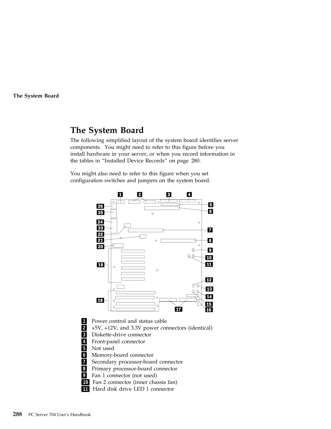
System Board
System Board
Changing Jumper and Switch Settings
Changing Jumper and Switch Settings
Changing a Jumper Setting
Setting Scsi ID Jumpers
Changing Jumper and Switch Settings
Default Scsi IDs for Hot-Swap Drives
Setting System-Board Configuration Jumpers
Setting System-Board Configuration Jumpers
1 of 2. Configuration Jumper Settings
Enabling Bios Recovery Mode J6A1
2 of 2. Configuration Jumper Settings
J6A1 Recovery Bios Recovery
Setting the Bios Boot Block Jumper J6A1
Setting the Video-Sleep-Register Address J6A2
J6A2 46E8 3C3 Video Sleep
Setting the Bios Write Jumper J6A4
Setting System-Board Configuration Switches
Setting System-Board Configuration Switches
Resetting Nvram and the RTC Switch S6A1-1
Configuration Switch Settings
S6A1
Clearing All Passwords Switch S6A1-2
Setting System-Board Configuration Switches
Appendix B. Notices
Trademarks
Trademarks
Accessing
Index
Adding
See also the Users Reference
Bays
Cables
See the Users Reference
Scsi ID
See also the Users Reference modem and fax requirements for
Nvram
See the Scsi Software Users Guide
PC Server 704 Users Handbook
See also the Users Reference
Diskettes
Drives location
See also the Users Reference adapters
Post
Features security
See the Users Reference fee services
See also the Users Reference arrays
LED
Internal drives
Jumpers
See also the Users Reference bank 113
See also the Users Reference adjusting
See also the Scsi Software Users Guide
See also the Users Reference capabilities 1 description
See also the Users Reference connector
See the Users Reference laser compliance statement x product
Optional power supply 3 options
Passwords
Svga
See also the Users Reference description
See also password
See also the Scsi Software Users
Adding board-support
Setting
See also jumpers changing 62 configuration
See the Users Reference system utility programs
See also the Users Reference sizes
Test programs
Index
IBM