Tuner Configuration
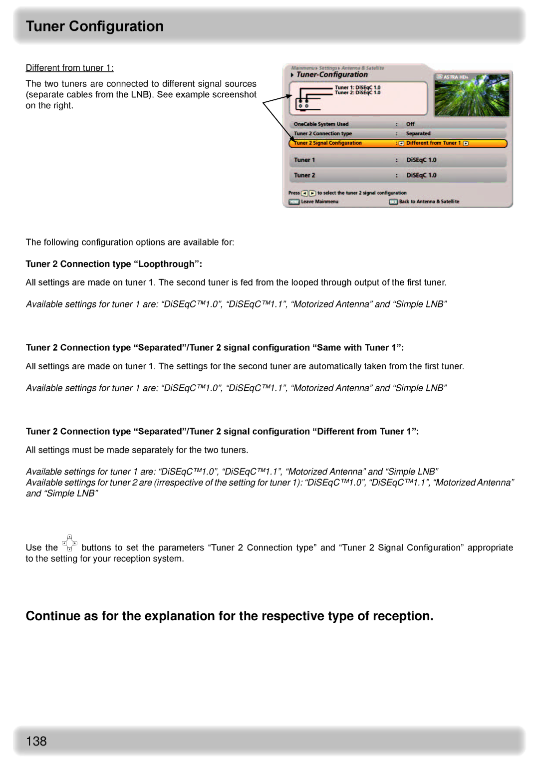
Different from tuner 1:
The two tuners are connected to different signal sources (separate cables from the LNB). See example screenshot on the right.
The following configuration options are available for:
Tuner 2 Connection type “Loopthrough”:
All settings are made on tuner 1. The second tuner is fed from the looped through output of the first tuner.
Available settings for tuner 1 are: “DiSEqC™1.0”, “DiSEqC™1.1”, “Motorized Antenna” and “Simple LNB”
Tuner 2 Connection type “Separated”/Tuner 2 signal configuration “Same with Tuner 1”:
All settings are made on tuner 1. The settings for the second tuner are automatically taken from the first tuner.
Available settings for tuner 1 are: “DiSEqC™1.0”, “DiSEqC™1.1”, “Motorized Antenna” and “Simple LNB”
Tuner 2 Connection type “Separated”/Tuner 2 signal configuration “Different from Tuner 1”:
All settings must be made separately for the two tuners.
Available settings for tuner 1 are: “DiSEqC™1.0”, “DiSEqC™1.1”, “Motorized Antenna” and “Simple LNB”
Available settings for tuner 2 are (irrespective of the setting for tuner 1): “DiSEqC™1.0”, “DiSEqC™1.1”, “Motorized Antenna” and “Simple LNB”
Use the buttons to set the parameters “Tuner 2 Connection type” and “Tuner 2 Signal Configuration” appropriate to the setting for your reception system.
Continue as for the explanation for the respective type of reception.