Merlin Legend
Troubleshooting in this binder
Ordering Information
Contents
Introduction
Installing Telephones and Adjuncts
Connecting Data Equipment
Upgrading the System
Unit Load Calculation Worksheet
Figures
Figures
Connecting the Control Unit to the Network Interface
Initializing and Testing the System
System Numbering Forms
Issue
Tables
Data Station Configurations Terminal Adapter Settings
Important Safety Instructions
Issue
Issue
Issue
Release 6.1 Enhancements August
Private Networking
Centralized Voice Messaging
Group Calling Enhancements
Transfer Redirect
Direct Station Selector
Call Forwarding
PRI Switch Type Test
Service Observing
Decrease in Call Set-Up Time
Win SPM
Windows NT Driver
Merlin Legend Communications System Release
Release 6.0 Enhancements February
Private Networks
Merlin Legend Communications System Release
Group Calling Enhancements
Queue Control
Prompt-Based Overflow
Centrex Transfer via Remote Call Forwarding
Computer Telephony Integration CTI
Authorization Codes Remote Call Forwarding
Release 5.0 Enhancements June
Basic Call Control
Screen Pop
HotLine Feature
Security Alert
Most Idle Hunt Type
Delay Announcement Devices
Enhanced Calls-in-Queue Alarm Thresholds
Release 4.2 Enhancements June
MLX-5 and MLX-5D Telephones
Merlin Legend Communications System Release
Merlin Legend Reporter
Maintenance Enhancements Change to Permanent Error Alarm
Release 4.1 Enhancements June
Coverage Timers Programmed for Individual Extensions
Night Service with Coverage Control
Enhanced Extension Information Report
Night Service Group Line Assignment
Forward on Busy
Support for Up to 200 Extensions
Support for National Isdn BRI Service
Release 4.0 Enhancements March
016 Tip/Ring Module
New Control Unit Modules
NI-BRI Module
Downloadable Firmware for the 016 and NI-BRI Modules
Voice Announce on Queued Call Console
Support for T1 Switched Digital Data Transmission
Forwarding Delay Option
Single-Line Telephone Enhancements
Seven-Digit Password for SPM
Time-Based Option for Overflow on Calling Group
Call Restriction Checking for Star Codes
Programmable Second Dial Tone Timer
Release 3.1 Enhancements March
Trunk-to-Trunk Transfer Set for Each Extension
Security Enhancements
Default Pool Dial-Out Code Restriction for All Extensions
Default Outward Restrictions for VMI Ports
New Maintenance Procedure for Testing Outgoing Trunks
Default Facility Restriction Level FRL for VMI Ports
Default for the Default Local Table
How to Use This Book
Intended Audience
Terms and Conventions Used
Lines, Trunks and Facilities
Old Term New Term
Product Safety Advisories
Typographical Conventions
Security
Security Alert
Telephone User Support
Related Documents
System Documents
Miscellaneous User Support
How to Comment on This Document
System Operator Support
Documentation for Qualified Technicians
About This Book How to Comment on This Document
Installation Sequence
Introduction
System Forms
Connecting the Network Interface
Installing the Control Unit
Installing Telephones Required Adjuncts Optional
Upgrading the System
Connecting Data Equipment
Programming the System
Introduction Upgrading the System
Merlin Legend Communications System Release
Installing the Control Unit
Overview
Environment
Ventilation
Electrical Noise/Radio-Frequency Interference
Backboard Requirements
Hardware Preassembly Process
Control Unit Requirements
Installing the Backboard
AC Power and Grounding
AC Grounding Requirements
AC Power Requirements Parameter Value
AC Outlet Tests
Unplug the circuit tester
Using an Ideal 61-035 Circuit Tester or Equivalent
Using a Volt-Ohm Milliammeter VOM
Grounding Requirements
Measuring the AC Outlet Voltages
Merlin Legend Communications System Release
Central Office and AC Grounds
Approved Grounds
Acceptable Water Pipe. Must be a metal, not plastic or vinyl
Central Office Trunk Protection
Heavy Lightning Protection
Installing 146A and 147A Protectors
Checking Unit Loads
Unit Loads for Hybrid/PBX Mode
Unit Loads
Installing the Basic Carrier
Unit Loads for Key or Behind Switch Mode
Mounting Surface
Installing the Power Supply
Turning Off the Power
Installing a Copper Shield
Merlin Legend Communications System Release
Installing a Copper Shield in the Power Supply
Installing the Power Supply Module Carrier
Installing the Ferrite Cores
Installing the Auxiliary Power Unit
Installing an Auxiliary Power Unit
Installing Expansion Carriers
Connecting the Carriers
Installing the Processor
Installing the Processor in the Carrier
Push firmly until the processor snaps into place
10. Installing the Processor into the Carrier
Installing the Modules
Guidelines
Installing Modules
Signaling Types
Tie Trunk Signaling
Signaling Modes
Tie Trunks
Mode
400EM Tie Trunk Module DIP Switches
Simplex Mode
Signaling Formats for the 400EM Tie Trunk Module
Merlin Legend Communications System Release
Labeling
12. Line/Trunk and Telephone Jack Locations on Each Module
Replacing a Module
13 on
13. Removing Modules from the Carrier
Connecting the Control Unit to an AC Outlet
Powering Up the System
Powering Down the System
Unplug the system from the AC outlet
Installing Telephones and Adjuncts
Installing Multi-Function Modules
Considerations
400B or 400B2 adapter D6AP cord
Risk of Electrical Shock Follow all warnings and cautions
Removing the User Card Tray and Line Cable
Releasing the Deskstand
Removing the Deskstand
Releasing the Module Cover Screw
Releasing the Module Cover
Removing the Module Cover
Removing an MFM Module
Installing an MFM Module
Install the new MFM. See Figure
10. Setting and Adjusting the MFM Jumpers
Multi-Function Module
11. Removing the Jack Guard
To remove the jack guard, see Figure
12. Placing the Module Cover into the Locating Slot
To replace the module cover, see -12, -13, and Figure
13. Lowering and Locking the Module Cover
14. Replacing and Tightening the Module Cover Screw
15. Replacing the Deskstand
16. Lowering the Deskstand and Locking into Place
17. Replacing the User Card Tray and Line Cable
Replace the user card tray and line cable. See Figure
Adjust the deskstand height. See Figure
Power up the telephone. See Figure
19. Powering Up the Telephone after Installing the MFM
Test the MFM for T/R operation
Installing Adjuncts
Attach the adjunct to the MFM. See Installing Adjuncts
20. Routing the Cords Through the Cord Channel
To connect an adjunct to a single-line telephone
General Purpose Adapter
To connect an adjunct to an analog multiline telephone
Dial Dictation Devices
Credit Card Verification Terminals
Group Calling Delay Announcement Devices
Fax Machines
Headsets
Headpieces
Manual Operation Analog Multiline Telephones Only
One-Touch Operation All Telephones
Loudspeaker Paging Systems
21. Manual and One-Touch Headset Operation
Dual-Tone Multifrequency Dtmf Signaling
22. Single-Zone Paging with PagePac Plus
23. Single-Zone Paging with Customer-Supplied Amplifier
24. Single-Zone Paging with Upam
Merlin Identifier
Modems
Music On Hold and Magic on Hold
Pagepac Outputs
Music Port Pagepac Plus
Supplemental Alerts
Supplemental Alert Adapter
Unsupported Telephones, Adjuncts Adapter
Supplemental Alert Adapter
Single-Line Telephones
Unsupported Telephones and Adjuncts
Single-Line Telephones
Single-Line Telephones in Release 3.0 and Later
Single-Line Telephones Supported by Release 3.0 and Later
Installing Direct Station Selectors
Wire the two DSSs. See Figure
Adjust the angle of the DSS
Install the D8AC cord on the DSS
28. Connecting One or More DSSs
Wire the telephone to the DSS units. See Figure
29. Wiring for Auxiliary Power
Label the DSS designation cards
Assembling MLX Telephones
30. Adjusting or Removing the Deskstand
Remove or adjust the deskstand. See Figure
31. Connecting the Line Cords
Connect the line cords. See Figure
Connect the handset
Label the extension identification card
33. Labeling the Extension
34. Removing the Handset Holder
Prepare the handset holder for wall-mounting
36. Replacing the Extension Label
Replace the extension label and plastic cover
37. Mounting the Backplate
Label the button assignment card
Pull the tab at the top of the plastic cover toward you
Adjust the contrast on the telephone’s display
Installing Cordless or Cordless/Wireless Telephones
MDW 9000/9010 Cordless/Wireless Telephones
MDC 9000 Cordless Telephone
Connecting Telephones to the Control Unit
Considerations
Merlin Legend Communications System Release
Wiring a Telephone for Two Voice Pairs
D8W
Removing Damaged Connecting Blocks
40. Removing the Connecting Block
Connecting the Control Unit to Network Interface
Wiring
Network Interfaces Description Adapter
Central Office Network Interface Codes
RJ21X Interface
RJ21X Network Interface Connector
Building the Wiring Field
RJ21X Wiring Field Hardware
RJ21X Wiring Field Tools
Using the D-Impact Tool to Seat the Conductors
RJ11 and RJ14 Interfaces
RJ2GX Interface
RJ48C/X Interface
Testing Trunks
Testing Loop-Start Trunks
Testing Ground-Start Trunks
Dial a telephone number to verify dialing
Testing NI-BRI Provisioning
Labeling Trunks
Label the jacks on the termination blocks
Installing the Channel Service Unit
Acculink CSUs
Merlin Legend Communications System Release
Front Panel
Wiring Two Switches Together
Back Panel
BLT
D8W BL/WR
Merlin Legend Communications System Release
Installing the PC, CAT, or Printer
Connecting a PC to the Control Unit
Connecting a PC Within 50 Feet
Connect the D8W cord
Connecting a PC More Than 50 Feet 15.2 m Away
Connecting a PC Within 50 ft .2 m
Merlin Legend Communications System Release
Plug the 2012D-50M transformer into a wall outlet
D6AP
Connecting a CAT to the Control Unit
Connecting a Printer to the Control Unit
Merlin Legend Communications System Release
Connecting a CAT and Printer on the Same AC Outlet
Connecting a CAT and Printer on a Different AC Outlet
Connecting a CAT and Printer on the Same AC Outlet
Merlin Legend Communications System Release
Merlin
Merlin Legend Communications System Release
Connecting a Printer Within 50 Feet 15.2 m
Connecting a Printer Within 50 ft .2 m
Connecting a Printer 50 Feet 15.2 m or More Away
Merlin Legend Communications System Release
Connecting a Printer More Than 50 ft .2 m Away
Connecting the 248B Adapter and the 2012D Transformer
Setting Printer Options and DIP Switches
Lucent Technologies 572 Printer Options
Connecting a Printer to the Control Unit Issue 1 August
Lucent Technologies 475/476 Printer DIP Switch Settings
Applications Printer DIP Switch Settings
Lucent Technologies Printer DIP Switch Settings
Merlin Legend Communications System Release
Connecting Data Equipment
Data Stations
Data Station Configurations
Modem Data Stations
Terminal Adapter Data Stations
Analog Voice and Modem Data Stations
GPA Settings
Setting Up
Connect the modem to the GPA
Connect the GPA to the analog multiline telephone
Analog Voice and Modem Data Equipment Configuration
Modem Data-Only Stations
Connect the modem to the control unit
Modem Data-Only Equipment Configuration
Modem Data and MLX Voice Equipment Configuration
MLX Voice and Modem Data Stations
Connect the modem to the MFM in the MLX telephone
Connect the MLX telephone to the control unit
MLX Voice and Terminal Adapter Data Stations
MLX Voice and Terminal Adapter Data Equipment Configuration
Connect the terminal adapter to the MLX telephone
Terminal Adapter Data-Only Stations
Merlin Legend Communications System Release
Terminal Adapter Data-Only Equipment Configuration
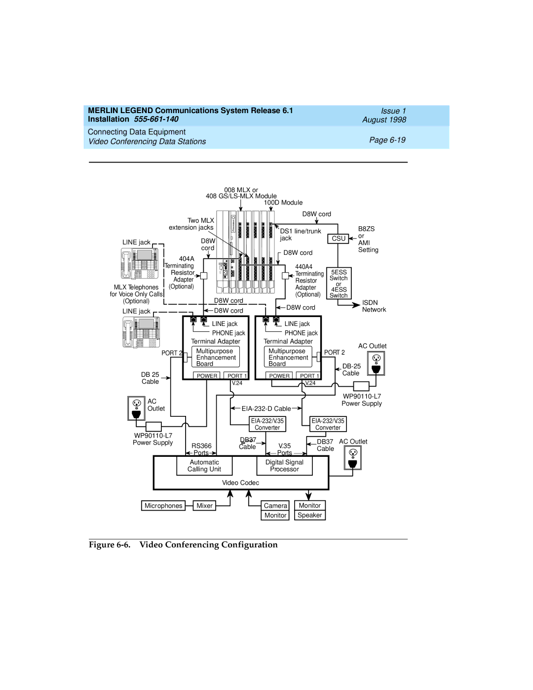
Video Conferencing Data Stations
Acculink 3150 CSU
Merlin Legend Communications System Release
Video Conferencing Configuration
Merlin Legend Communications System Release
Terminal Adapter and CSU Settings
Terminal Adapter Settings
Merlin Legend Communications System Release
Initializing and Testing the System
Initializing the System
Restoring from the System Programming Disk
Programming Guides
Restoring from the Translation Memory Card
Perform a System Erase frigid start
Testing MLX Telephones
Setting the Time and Date
Testing the System
Initializing and Testing the System
Testing MLX Display Telephones
Testing MLX Telephones with MFMs
Turn off the Message light
Testing Telephones for Dial Tone
Press any button
Testing Telephones for Outside Dial Tone
Testing Analog Multiline Single-Line Telephones
If the extension is toll-restricted, place a toll call
Dial followed by the trunk ID number 01 through
Testing did Trunks
Testing Tie Trunks
At both telephones, hang up
Testing Two-Way Automatic-Start Tie Trunks
Testing Incoming Automatic-Start Tie Trunks
Testing Incoming Dial-Repeating Tie Trunks
Testing Outgoing Automatic-Start Tie Trunks
Testing Two-Way Dial-Repeating Tie Trunks
Testing Outgoing Dial-Repeating Tie Trunks
You should hear ringing
Testing BRI Trunks
Testing Selected System Features
ARS and Smdr Tests
Group Calling Test
System Speed Dial Test
Coverage Test
Testing the DSS
Testing Night Service
Testing the Dictation System
Make an announcement into the handset
Testing the Paging System
Testing Music On Hold
Hang up Repeat Steps 1 through 3 for all paging zones
Testing the Power Failure Transfer Jacks
Ground-Start Button
If you hear reorder tone, try again
Testing Touch-Tone Receivers
Have that person call the number after you hang up
Repeat the test for each TTR
Installing the Control Unit’s Housing
Installing the Top Cover
Top cover Empty module
Installing the Front Cover
Installing the Control Unit Front Cover
Installing Applications
Voice Messaging Systems Touch-Tone Receivers
Automated Document Delivery System
Call Accounting System
Hardware Requirements
Hardware and Software Requirements
Merlin Legend Communications System Release
Call Accounting Terminal
CAS Documentation
Considerations
Call Management System
CAT Documentation
Hardware and Software Requirements
CMS Documentation
Conversant
Integrated Solution
Conversant Intro Documentation
Security Alert
Hardware Requirements
Lucent Technologies Attendant†
Security Alert
Merlin Mail
Merlin Mail Ports Required
Merlin Legend Communications System Release
Merlin PFC†
Hybrid/PBX and Key Modes
PassageWay Direct Connect Solution
Behind Switch Mode
Considerations
System Programming Maintenance SPM
Considerations
Installing a CTI Link
New Installation Considerations
Install Merlin Legend hardware
Plug in the CTI link, if unplugged
Link Reinstatement
Program the communications system
Resume Merlin Legend alarming for the CTI link
Resume CTI link traffic
Merlin Legend Communications System Release
Upgrading the System
Upgrading to Release
Install the new processor module
Remove the control unit housing
Power down the system
Install SPM Back up system programming
Backing Up System Programming
Removing the Control Unit Housing
Upgrading the System Powering Down the System
Powering Down the System
Install any expansion carriers
Upgrading the Control Unit
Program the system
Test the system
Removing a Module from the Carrier
Replacing the Housing Clips
Replacing a Module in the Carrier
Modifying the Processor for Key Mode
Removing the Processor Module Cover
Removing the Processor Module Circuit Board
Changing the Key Mode Switch Position to Closed
If applicable, program new features
Completing the Upgrade
Convert the backup file
Install SPM
Program the system
Install the Release 4.0 processor module in the carrier
If applicable, program new features
Replacing the Control Unit Housing
Release 2.0 or Earlier
Installing the Control Unit Housing
Merlin Legend Communications System Release
System Numbering Forms
Form 2a, System Numbering Extension Jacks
Renumber System
Merlin Legend Communications System Release
Form 2b, System Numbering Digital Adjuncts
MLX
Form 2c, System Numbering Line/Trunk Jacks
Loop-Start Reliable Disconnect
Form 2d, System Numbering Special Renumbers
Code†
Unit Load Calculation Worksheet
Unit Load Worksheet
Module Qty Unit Load = Total
Network Access Lines
Telephones
Optional Equipment
Unit Load Calculation Worksheet B-6 Unit Load Worksheet
Calculate the unit loads for slots 5 and 6 of the carrier
Unit Load Calculation Worksheet B-8 Unit Load Worksheet
Unit Load Calculation Worksheet B-9 Unit Load Worksheet
Unit Load Calculation Worksheet B-10 Unit Load Worksheet
Index
Issue 1 August IN-2
Issue 1 August IN-3
Issue 1 August IN-4
Issue 1 August IN-5
Issue 1 August IN-6
IN-7
Issue 1 August IN-8
Issue 1 August IN-9
Index IN-10
Issue 1 August IN-11
Index IN-12
Issue 1 August IN-13
Issue 1 August IN-14
Issue 1 August IN-15
Index IN-16