MERLIN LEGEND Communications System Release 6.1 | Issue 1 | ||
Installation | August 1998 | ||
Installing Telephones and Adjuncts | Page | ||
Installing | |||
|
|
|
|
|
|
|
|
Locking Tab |
|
|
|
. |
| . | . |
. . |
|
| |
|
| . | |
.. . |
|
|
|
. . |
|
|
|
. | . |
|
|
. | . |
|
|
| . . |
|
|
Socket |
|
|
|
| . |
| . |
Connector |
|
| |
|
|
| |
Pins |
|
|
|
. | . | . |
| . |
|
.
... ![]()
![]() .
.![]() .
.
.![]()
.
.
.
. | . | . |
|
Locking Tab |
|
|
|
|
|
|
. . | . . . . . . | |||||
|
| . | . | . | ||
.. . | . . |
|
|
|
| |
|
|
|
|
| ... .. | |
|
|
|
|
|
| |
| . |
| . |
|
| . |
|
|
|
|
| ||
. | . |
| . . |
|
| |
| . . | . |
|
| ||
Line Jack |
|
|
|
|
| |
|
|
| . |
|
| |
|
| . | . |
|
| |
|
|
|
|
| ||
|
|
|
|
|
| |
|
|
|
|
| . | . . |
|
|
|
|
|
| |
![]()
![]() Handset Jack
Handset Jack
Locking Tab
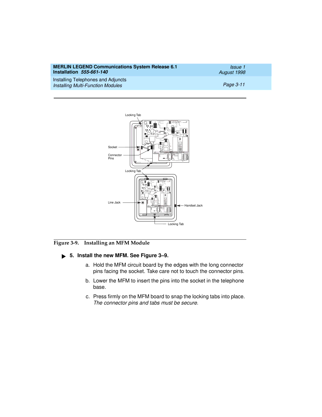
Figure 3-9. Installing an MFM Module
! Install the new MFM. See Figure 3–9.
a.Hold the MFM circuit board by the edges with the long connector pins facing the socket. Take care not to touch the connector pins.
b.Lower the MFM to insert the pins into the socket in the telephone base.
c.Press firmly on the MFM board to snap the locking tabs into place. The connector pins and tabs must be secure.