Using the BayStack 350 10/100/1000 Series Switch
Front-Panel
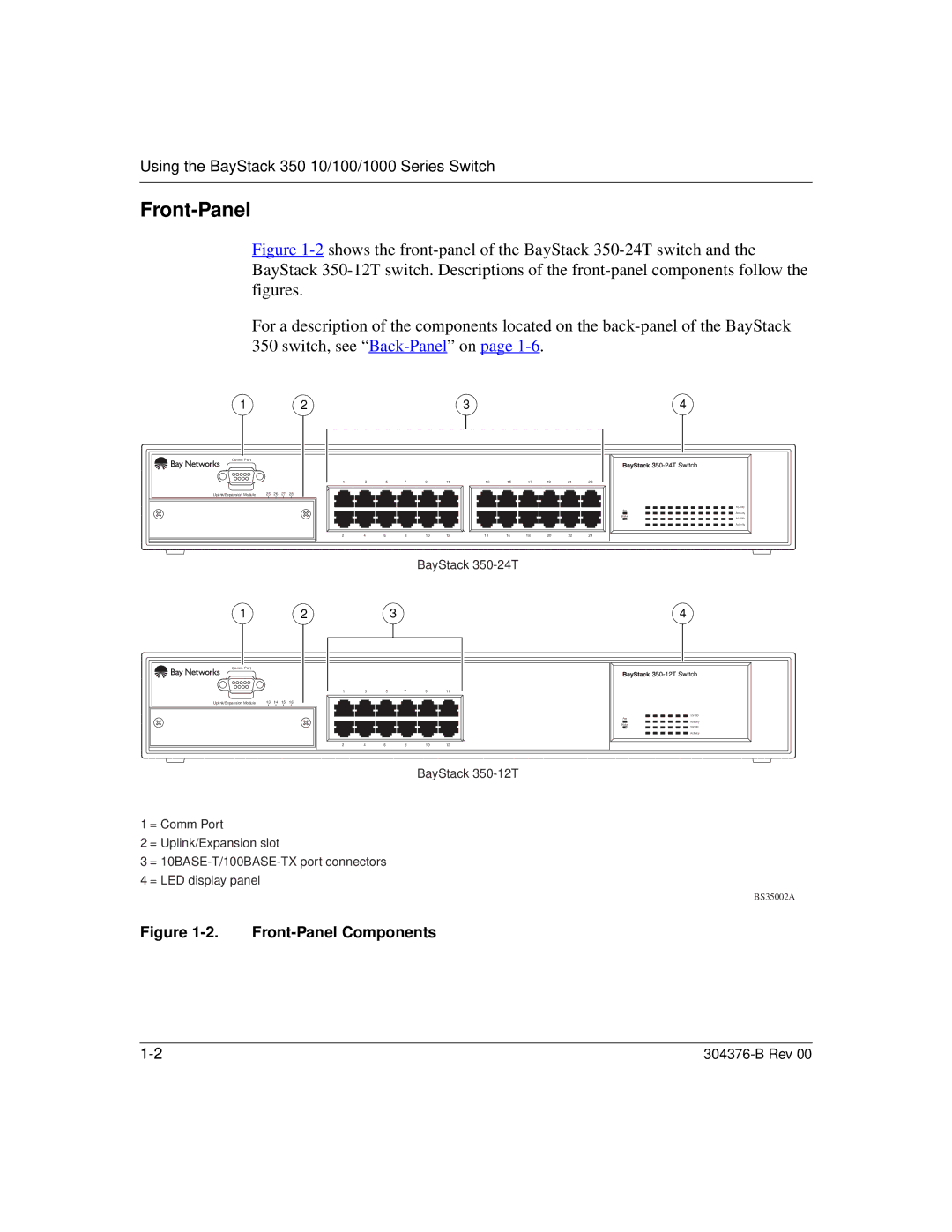
Figure 1-2 shows the front-panel of the BayStack 350-24T switch and the BayStack 350-12T switch. Descriptions of the front-panel components follow the figures.
For a description of the components located on the back-panel of the BayStack
350switch, see “ Back-Panel” on page 1-6.
1 | 2 | 3 | 4 |
Comm Port |
|
|
|
|
|
|
|
|
|
|
|
|
|
| 1 | 3 |
| 5 | 7 | 9 | 11 | 13 | 15 | 17 | 19 | 21 | 23 |
Uplink/Expansion Module | 25 26 27 28 |
|
|
|
|
|
|
|
|
|
|
|
|
| 2 | 4 | 6 |
| 8 | 10 | 12 | 14 | 16 | 18 | 20 | 22 | 24 |
![]()
![]()
![]()
![]() 3
3![]()
![]()
![]()
![]()
![]()
![]()
![]()
10/100
Pwr
Activity
Status
10/100
Activity
12
Comm Port
Uplink/Expansion Module | 13 14 15 16 |
BayStack
3
1 | 3 |
| 5 | 7 | 9 | 11 |
2 | 4 | 6 |
| 8 | 10 | 12 |
4
![]()
![]()
![]()
![]() 3
3![]()
![]()
![]()
![]()
![]()
![]()
![]()
10/100
Pwr
Activity
Status
10/100
Activity
BayStack
1 = Comm Port
2 = Uplink/Expansion slot
3 =
4 = LED display panel
BS35002A
Figure 1-2. Front-Panel Components
|