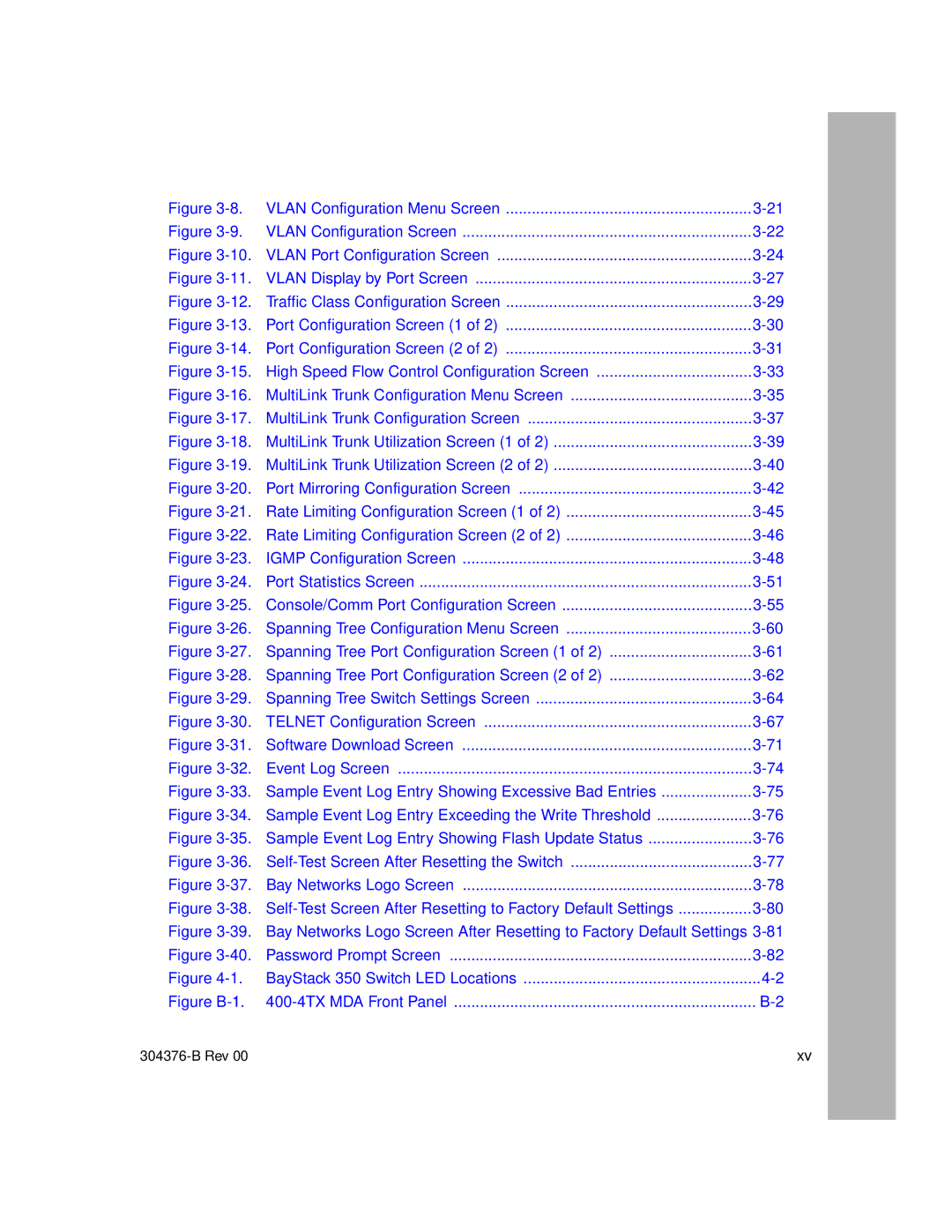
Figure | VLAN Configuration Menu Screen | |
Figure | VLAN Configuration Screen | |
Figure | VLAN Port Configuration Screen | |
Figure | VLAN Display by Port Screen | |
Figure | Traffic Class Configuration Screen | |
Figure | Port Configuration Screen (1 of 2) | |
Figure | Port Configuration Screen (2 of 2) | |
Figure | High Speed Flow Control Configuration Screen | |
Figure | MultiLink Trunk Configuration Menu Screen | |
Figure | MultiLink Trunk Configuration Screen | |
Figure | MultiLink Trunk Utilization Screen (1 of 2) | |
Figure | MultiLink Trunk Utilization Screen (2 of 2) | |
Figure | Port Mirroring Configuration Screen | |
Figure | Rate Limiting Configuration Screen (1 of 2) | |
Figure | Rate Limiting Configuration Screen (2 of 2) | |
Figure | IGMP Configuration Screen | |
Figure | Port Statistics Screen | |
Figure | Console/Comm Port Configuration Screen | |
Figure | Spanning Tree Configuration Menu Screen | |
Figure | Spanning Tree Port Configuration Screen (1 of 2) | |
Figure | Spanning Tree Port Configuration Screen (2 of 2) | |
Figure | Spanning Tree Switch Settings Screen | |
Figure | TELNET Configuration Screen | |
Figure | Software Download Screen | |
Figure | Event Log Screen | |
Figure | Sample Event Log Entry Showing Excessive Bad Entries | |
Figure | Sample Event Log Entry Exceeding the Write Threshold | |
Figure | Sample Event Log Entry Showing Flash Update Status | |
Figure | ||
Figure | Bay Networks Logo Screen | |
Figure | ||
Figure | Bay Networks Logo Screen After Resetting to Factory Default Settings | |
Figure | Password Prompt Screen | |
Figure | BayStack 350 Switch LED Locations | |
Figure | ||
| xv |
