Using the BayStack 350 10/100/1000 Series Switch
Table | LED Descriptions (continued) | |||
|
|
|
|
|
Label | Type | Color | State | Meaning |
|
|
|
|
|
Status | System status | Green | On | |
|
|
| Blinking | A nonfatal error occurred during the |
|
|
| Off | The switch failed the |
10/100 | 10/100 Mb/s | Green | On | The corresponding port is set to operate at 100 Mb/s and |
| port speed |
|
| the link is good. |
| indicator |
|
|
|
|
| Green | Blinking | The corresponding port has been disabled by software. |
|
| Amber | On | The corresponding port is set to operate at 10 Mb/s and |
|
|
|
| the link is good. |
|
| Amber | Blinking | The corresponding port has been disabled by software. |
|
|
| Off | The link connection is bad or there is no connection to |
|
|
|
| this port. |
Activity | Port activity | Green | Blinking | Indicates network activity for the corresponding port. A |
|
|
|
| high level of network activity can cause the LEDs to |
|
|
|
| appear to be on continuously. |
|
|
|
|
|
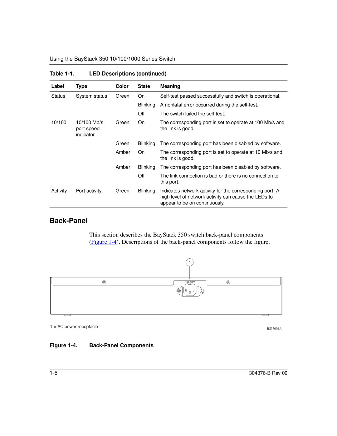
Back-Panel
This section describes the BayStack 350 switch
(Figure 1-4). Descriptions of the back-panel components follow the figure.
1
1 = AC power receptacle | BS35004A |
|
Figure 1-4. Back-Panel Components
|