BayStack 350 10/100/1000 Series Switches
S1 |
|
|
|
|
|
|
|
| VLAN 3 |
|
|
|
|
| VLAN 2 | VLAN 1 |
|
Port 2 | Port 4 | Port 10 | Port 8 | Port 6 | Port 11 |
PVID = 2 |
|
| PVID = 3 | PVID = 1 |
|
V2 | V2 | V2 | V3 | V1 | V2 |
Key
VLAN 1 (PVID = 1)
VLAN 2 (PVID = 2)
VLAN 3 (PVID = 3)
BS35019A
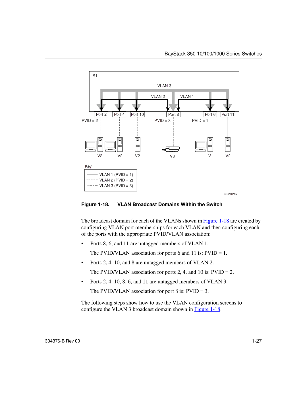
Figure 1-18. VLAN Broadcast Domains Within the Switch
The broadcast domain for each of the VLANs shown in Figure
•Ports 8, 6, and 11 are untagged members of VLAN 1.
The PVID/VLAN association for ports 6 and 11 is: PVID = 1.
•Ports 2, 4, 10, and 8 are untagged members of VLAN 2.
The PVID/VLAN association for ports 2, 4, and 10 is: PVID = 2.
•Ports 2, 4, 10, 8, 6, and 11 are untagged members of VLAN 3. The PVID/VLAN association for port 8 is: PVID = 3.
The following steps show how to use the VLAN configuration screens to configure the VLAN 3 broadcast domain shown in Figure
|