Programmer’s Guide
Safety Information
Limitation of Warranty
Page
Contents
Programming Command Cross References
Contents
Contents
Contents
Contents
List of Commands
List of Commands
List of Commands
List of Commands
List of Commands
List of Commands
List of Commands
List of Commands
List of Commands
List of Commands
List of Commands
List of Commands
List of Commands
List of Commands
List of Commands
List of Commands
List of Commands
List of Commands
List of Commands
List of Commands
List of Commands
List of Commands
List of Commands
List of Commands
Preparing for Use
Digital Communications Measurements Information
What’s in This Chapter?
Chapter
Available Modes and Measurements
Programming the Transmitter Tester
Instselect Wcdma
Instselect Nadc
Available Measurement Personality Options
Installing Optional Measurement Personalities
Available Personality Options File Size VSA A.05.20
Loading an Optional Measurement Personality
Installing a License Key
Viewing a License Key
Using the Uninstall Key
Using the Uninstall key does not remove the personality from
Three Basic Steps in a Measurement
Writing Your First Program
Programming a Measurement
File Naming Rules
HP/Agilent 24542U Cable
Cables for Connecting to RS-232
HP/Agilent F1047-80002 Cable
HP/Agilent 13242G Cable
HP/Agilent C2913A/C2914A Cable
HP/Agilent 24542U Cable with 5181-6641 Adapter
12 HP/Agilent 24542U Cable with 5181-6639 Adapter
15 HP/Agilent F1047-80002 Cable with 5181-6642 Adapter
Connecting to a LAN Server
Connecting to a Gpib Server
Programming Fundamentals
Programming Fundamentals
Scpi Language Basics
Command Keywords and Syntax
Command Syntax Sample Valid Commands
Creating Valid Commands
Parameters indicates
Special Characters in Commands
OFFON01
Parameters in Commands
Variable Parameters
Block Program Data
Putting Multiple Commands on the Same Line
Scpi Termination and Separator Syntax
SENSe POWer
Improving the Speed of Your Measurements
Turn off the display updates
Use binary data format instead of Ascii
Minimize the number of Gpib transactions
Improving the Speed of Your Measurements
Consider using LAN instead of Gpib
Minimize DUT/instrument setup changes
Avoid automatic attenuator setting
Avoid unnecessary use of *RST
Avoid using RFBurst trigger for single burst signals
Optimize your GSM output RF spectrum switching measurement
STATusOPERationENABle
Are you making a single burst measurement?
Improving the Speed of Your Measurements
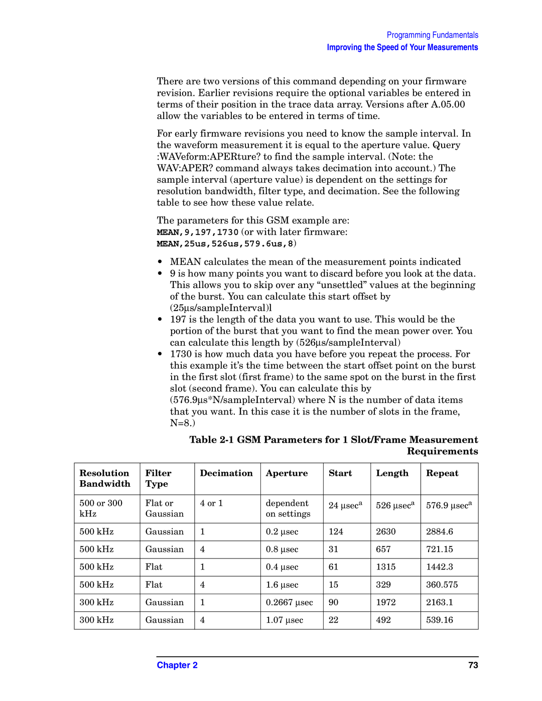
GSM Parameters for 1 Slot/Frame Measurement Requirements
MEAN,25us,526us,579.6us,8
300 kHz Flat 6667 ∝sec 789 865.31 197 216.33
Preventing Local or Remote Interference While Programming
Using the Status Registers
Using the Instrument Status Registers
What are the Status Registers?
Using the Instrument Status Registers
Polling method Service request SRQ method
Why Would You Use the Status Registers?
Using the Instrument Status Registers
Using a Status Register
Using the Instrument Status Registers
Overall Status Register System
Status Byte Register
Bit Description
Using the Instrument Status Registers
Standard Event Status Register
Standard event status register contains the following bits
Operation and Questionable Status Registers
Using ftp for File Transfers
Using the LAN to Control the Analyzer
Ftp Commands
Standard Unix FTP Command
Mget remotefile
On unix
Using Telnet to Send Commands
On a PC
Unix Telnet Example
Example Telnet Session
Standard Unix Telnet Command
Using Socket LAN to Send Commands
Setting Up Your Analyzer for Socket Programming
Collecting Sicl LAN Set-up Information
Using Sicl LAN to Control the Analyzer
Configuring Your PC as a Sicl LAN Client
Configuring Your Analyzer as a Sicl LAN Server
Controlling Your Analyzer with Sicl LAN and HP/Agilent VEE
I/OInstrument Manager Menu
Adding Your Analyzer as a VEE Device
Sending Scpi Commands Directly to your Analyzer
Chapter 101
Where 18 is the device address for the analyzer
Sample VEE Screen
Using HP/Agilent VEE Over Socket LAN
Using a C Program Over Socket LAN
Using a Java Applet Over Socket LAN
Troubleshooting the Initial Connection
General LAN Troubleshooting
Communications Not Established
You cannot connect to the analyzer
You cannot telnet to the command parser port
You cannot access the file system via ftp
You get an operation timed-out message
If all else fails
Pinging the Analyzer from Your Computer or Workstation
Error Messages
Normal Response for Unix
Normal Response for DOS or Windows
Intermittent Response
Standard Unix Ping Command Synopsis ping -r-v-o
Chapter 111
Cross-Over Patch Cable Wiring cross-over end
Typical Example Program Contents
Programming Using VTL
Compiling and Linking a VTL Program
Linking to VTL Libraries
Bit Applications
\VXIPNP\WIN95\INCLUDE
Example Program
Opening a Session
Including the Visa Declarations File
Device Sessions
ViOpen sesn, rsrcName, accessMode, timeout
Functions
Addressing a Session
Instr
Board
Closing a Session
Overview of the Gpib Bus
Gpib Command Statements
Gpib Instrument Nomenclature
Chapter 123
Overview of the RS-232 Bus
Settings for the Serial Interface
Handshake and Baud Rate
Modem Line Handshaking
Character Format Parameters
Data Transfer Errors
Programming Examples
Types of Examples
Using Markers
130
Chapter 131
Agilent Technologies
Saving Binary Trace Data in an Ascii File
Chapter 133
134
Chapter 135
Saving Ascii Trace Data in an Ascii File
Chapter 137
138
Saving and Recalling Instrument State Data
140
Chapter 141
142
Performing Alignments and Getting Pass/Fail Results
144
This is the C programming example ACPR.c
Making an Acpr Measurement in cdmaOne Option BAC
146
Chapter 147
Using C Programming Over Socket LAN
Chapter 149
150
Chapter 151
152
Chapter 153
154
Chapter 155
156
Chapter 157
158
Chapter 159
160
Chapter 161
162
Chapter 163
164
Chapter 165
166
Chapter 167
Synopsis
Using C Programming Over Socket LAN Windows NT
Chapter 169
170
URL
Using Java Programming Over Socket LAN
172
Chapter 173
174
Chapter 175
176
Chapter 177
178
Chapter 179
Using Java Programming Over Socket LAN 180
Programming Command Cross References
Display Views
Functional Sort of Scpi Commands
Chapter 183
184
Language Reference
Scpi Command Subsystems
Standard Event Status Enable
Common Ieee Commands
Calibration Query
Clear Status
Identification Query
Standard Event Status Register Query
Instrument State Query
Operation Complete Query
Operation Complete Command
Systset #NMMMMstatedata
Systset state data
Query Instrument Options
Reset
Recall
RCL register
Save
Service Request Enable
Read Status Byte Query
SAV register
Self Test Query
Trigger
Wait-to-Continue
ABORt Subsystem
Abort Command
ABORt
CALCulate Subsystem
Adjacent Channel Power-Limit Test
ACP Limits
CALCulateACPLIMitSTATe OFFON01 CALCulateACPLIMitSTATe?
Test Current Results Against all Limits
Baseband IQ Commands
Data Query
BbIQ in Spectrum I/Q Marker Query
Calculate/Compress Trace Data Query
Measurement Available Traces Markers Available?
CALCDATA2COMP? MEAN,24e-6,526e-6 These
198
Chapter 199
Calculate Peaks of Trace Data
Use CALCDATA4PEAK? -40,10,FREQ to identify
CALCulateMARKers Subsystem
Ascii
Service Mode measurement key words
Basic Mode measurement key words
CdmaOne Mode measurement key words
Cdma2000 Mode measurement key words
IDEN Mode measurement key words
GSM Mode measurement key words
Nadc Mode measurement key words
PDC Mode measurement key words
CALCulateSPECtrumMARKer2MAXimum
Example
Markers All Off on All Traces
CALCulatemeasurementMARKerAOFF
Marker Peak Maximum Search
Marker Function Result
Marker Peak Minimum Search
Marker Mode
CALCulatemeasurementMARKer1234MINimum
CALCSPECMARK2 on
Marker On/Off
Marker to Trace
208
Chapter 209
210
CALCSPECMARK2X 1.2e6 Hz
Marker X Value
Marker X Position
Marker Readout Y Value
Power Statistic CCDF-Store Reference
CALCulatemeasurementMARKer1234Y?
CALCulatePSTatisticSTOReREFerence ONOFF10
Calibration Abort
CALibration Subsystem
Align the ADC Auto-range Threshold
Align the ADC Dither Center Frequency
Align the ADC RAM Gain
Align the ADC Offset
Align All Instrument Assemblies
Calibrate the Attenuator
Calibration Comb Alignment
Automatic Alignment
CALibrationAUTO Offalerton CALibrationAUTO?
CALibrationCOMB CALibrationCOMB?
Calibration Display Detail
Turn Background Calibration Corrections Off
Align the Image Filter Circuitry
CALibrationDISPlayLEVel Offlowhigh CALibrationDISPlayLEVel?
CALibrationFREQuencyREFerenceAADJust
Auto Adjust the Internal 10 MHz Frequency Reference
Align the if Flatness
CALibrationFLATnessIF CALibrationFLATnessIF?
Baseband I/Q IQ Common Mode Response Null
Baseband I/Q Commands
Align the ADC
Align the if Gain
Baseband I/Q IQ Flatness Calibration
Calibrate the Nominal System Gain
Baseband I/Q IQ Offset Calibration
Align the if
Load the Factory Default Calibration Constants
Align the RF
Align the Narrow LC Prefilter
Align the Narrow Crystal Prefilter
Align the Wide LC Prefilter
Align the Wide Crystal Prefilter
MHz Reference Alignment Signal
Adjust the Level of the 321.4 MHz Alignment Signal
CALibrationREF50AMPL power CALibrationREF50AMPL?
CALibrationREF321 CALibrationREF321?
CALibrationREF50ANOW
Internal 50 MHz Amplitude Reference Alignment Control
CALibrationREF50DOIT CALibrationREF50DOIT?
CALibrationREF50EXIT
CALibrationREF50ENTer
Query the Absolute Level for the 50 MHz Amplitude Reference
CALibrationREF50LASTALEVel?
Query the ALC DAC Value for the 50 MHz Amplitude Reference
Select Time Corrections
CALibrationREF50LASTALCDac?
CALibrationTCORrections Autoonoff
CALibrationTRIGgerDELay CALibrationTRIGgerDELay?
Align the Trigger Delay
Align the Trigger Interpolator
Calibration Wait
Configure the Selected Measurement
CONFigure Subsystem
Configure Query
CONFiguremeasurement
DISPlay Subsystem
Adjacent Channel Power View Selection
Date and Time Display
DISPlayACPVIEW BGRaphSPECtrum DISPlayACPVIEW?
DISPlayENABle OFFON01 DISPlayENABle?
Access
Display Annotation Title Data
Turn the Display On/Off
Spectrum Y-Axis Scale/Div
Select Display Format
DISPlayFORMatTILE
DISPlayFORMatZOOM
Spectrum Y-Axis Reference Level
DISPlayTRACenSTATe OFFON01 DISPlayTRACenSTATe?
Turn a Trace Display On/Off
Chapter 233
234
Waveform Y-Axis Scale/Div
Waveform Y-Axis Reference Level
Chapter 237
Fetch the Current Measurement Results
FETCh Subsystem
FETChmeasurementn?
Byte Order
FORMat Subsystem
Numeric Data format
FORMatBORDer NORMalSWAPped FORMatBORDer?
240
Screen Printout Destination
HCOPy Subsystem
Custom Printer Color Capability
HCOPyDESTination FPANelPRINter HCOPyDESTination?
Printer Type
Custom Printer Language
HCOPyDEViceLANGuage PCL3PCL5 HCOPyDEViceLANGuage?
HCOPyDEViceTYPE CUSTomNONE HCOPyDEViceTYPE?
Print a Hard Copy
Color Hard Copy
Form Feed the Print Item
Orientation
Reprint the Last Image
Number of Items Printed on a
HCOPyPAGEPRINts HCOPyPAGEPRINts?
HCOPyREPRintIMMediate
Screen Dump Image Inverting
Screen Dump Query
HCOPySDUMpDATA? Gifbmpwmf
GIF
HCOPySDUMpIMMediate
Screen Dump to a Printer
Take New Data Acquisition for Selected Measurement
INITiate Subsystem
Continuous or Single Measurements
INITiatemeasurementname
Restart the Measurement
Take New Data Acquisitions
INITiateIMMediate
Initimm
Baseband I/Q Select Input Impedance
INPut Subsystem
Baseband I/Q Select Input Impedance Reference
INPutIMPedanceIQ U50B600U1MB1M INPutIMPedanceIQ?
Baseband I/Q I Input DC Offset
Baseband I/Q Activate IQ Alignment
Baseband I/Q Q Input DC Offset
Chapter 251
Catalog Query
INSTrument Subsystem
Select Application by Number
INSTrumentSELect
Select Application
INSTrumentSELect?
Instsel GSM
CONFigure, FETCh, MEASure, Read Interactions
MEASure Group of Commands
Measure Commands
MEASuremeasurementn?
Measurement Group of Commands Configure Commands
Read Commands
Fetch Commands
READmeasurementn?
258
CONFigureACP FETChACPn? READACPn? MEASureACPn?
Adjacent Channel Power Ratio ACP Measurement
Measurement Results Available
260
Chapter 261
262
Chapter 263
264
Chapter 265
266
MHz Amplitude Reference Measurement
Channel Power Measurement
Power Statistics Ccdf Measurement
270
CONFigurePVTime FETChPVTimen? READPVTimen? MEASurePVTimen?
Power vs. Time Measurement
272
Chapter 273
Sensor Measurement
Spectrum Frequency Domain Measurement
276
Chapter 277
Waveform Time Domain Measurement
Timebase Frequency Measurement
Chapter 279
280
Un-install Application
Install Application
MEMoryINSTallAPPLication filename
MEMoryUNINstallAPPLication filename
Memory Available or In-Use
MMEMory Subsystem
Select a Memory Device
MMEMoryFREE?
MMEMorySTOReSCReenIMMediate filename
Store a Screen Image in a Graphic File
Mmemstorescreenfiletype
Screen Image Background
Screen File Type
MMEMorySTOReSCReenFILETYPE Gifbmpwmf
Initiate and Read Measurement Data
Read Subsystem
Adjacent Channel Power-Average Count
Adjacent Channel Power Measurement
Adjacent Channel Power-Averaging State
SENSe Subsystem
Adjacent Channel Power-Type of Carrier Averaging
Adjacent Channel Power-Averaging Termination Control
Adjacent Channel Power-Carrier Channel BW
SENSeACPAVERageTYPE MAXimumRMS SENSeACPAVERageTYPE?
CdmaOne, W-CMDA Trial & Arib mode
Adjacent Channel Power-Dynamic Range
Adjacent Channel Power-Fast Mode Relative Attenuation
Adjacent Channel Power-Fast Mode ADC Range
Adjacent Channel Power-Root Raised Cosine Filter Control
Adjacent Channel Power-Root Raised Cosine Filter Alpha
Adjacent Channel Power-Reference Channel FFT Segments
Adjacent Channel Power-Frequency Span Query
Adjacent Channel Power-Reference Channel FFT Segments State
SENSeACPFFTSegmentAUTO OFFON01 SENSeACPFFTSegmentAUTO?
SENSeACPFREQuencySPAN?
Adjacent Channel Power-Offset Frequency
Adjacent Channel Power-Offset Frequency Absolute Limit
Adjacent Channel Power-Offset Frequency Relative Limit
Adjacent Channel Power-Offset Frequency Power Mode
Adjacent Channel Power-Offset Frequency Control
Adjacent Channel Power-Absolute Amplitude Limits
Adjacent Channel Power-Offset Frequency Test Mode
SENSeACPOFFSetABSolute power SENSeACPOFFSetABSolute?
SENSeACPOFFSetnLISTABSolute Power,power,power,power,power
SENSeACPOFFSetnLISTABSolute?
SENSeACPOFFSetLISTBANDwidthBWIDth?
Adjacent Channel Power-Type of Offset Averaging
SENSeACPOFFSetnLISTBANDwidthBWIDth?
SENSeACPOFFSetnLISTnBANDwidthBWIDth?
SENSeACPOFFSetLISTFFTSegmentAUTO?
Adjacent Channel Power-FFT Segments
SENSeACPOFFSetFREQuency foffset SENSeACPOFFSetFREQuency?
Chapter 301
Adjacent Channel Power-Automatic Measurement Points
Adjacent Channel Power-Number of Measured Points
SENSeACPOFFSetLISTPOINtsAUTO?
Adjacent Channel Power-Relative Attenuation Control
Adjacent Channel Power-Relative Attenuation
SENSeACPOFFSetRCARrier relpower SENSeACPOFFSetRCARrier?
SENSeACPOFFSetRPSDensity relpower SENSeACPOFFSetRPSDensity?
SENSeACPOFFSetLISTRPSDensity?
SENSeACPOFFSetLISTSIDE?
Adjacent Channel Power-Select Sideband
SENSeACPOFFSetnLISTnSTATe?
Adjacent Channel Power-Control Offset Frequency List
Chapter 309
SENSeACPOFFSetLISTSWEepTIMEAUTO?
Adjacent Channel Power-Automatic Sweep Time
SENSeACPOFFSetLISTTEST?
SENSeACPOFFSetnLISTTEST?
Chapter 311
SENSeACPPOINtsAUTO OFFON01 SENSeACPPOINtsAUTO?
SENSeACPPOINts integer SENSeACPPOINts?
SENSeACPSPECtrumENABle OFFON01 SENSeACPSPECtrumENABle?
Adjacent Channel Power-Spectrum Trace Control
Adjacent Channel Power-Sweep Mode Resolution Bandwidth
SENSeACPSWEepBANDwidthBWIDthRESolutionAUTO
Adjacent Channel Power-Sweep Mode Resolution BW Control
SENSeACPSWEepBANDwidthBWIDthRESolutionAUTO?
Adjacent Channel Power-Sweep Mode Detection
SENSeACPSWEepTIMEAUTO OFFON01 SENSeACPSWEepTIMEAUTO?
Adjacent Channel Power-Sweep Type
SENSeACPSWEepTYPE FASTFFTSWEep SENSeACPSWEepTYPE?
SENSeACPSWEepTYPE FFTSWEep SENSeACPSWEepTYPE?
Adjacent Channel Power-Trigger Source
FFT
Baseband I/Q Select I/Q Power Range
Adjacent Channel Power-Power Reference
SENSeACPTYPE PSDRefTPRef SENSeACPTYPE?
Baseband I/Q Select I/Q Voltage Range
Channel Commands
SENSeVOLTageIQRANGeUPPer level SENSeVOLTageIQRANGeUPPer?
Select the ARFCN-Absolute RF Channel Number
SENSeCHANnelARFCnRFCHannelBOTTom
Select the Lowest Arfcn
SENSeCHANnelARFCnRFCHannelMIDDle
Select the Middle Arfcn
Select the Highest Arfcn
SENSeCHANnelARFCnRFCHannelTOP
Burst Type
SENSeCHANnelBURSt NORMalSYNCACCess SENSeCHANnelBURSt?
SENSeCHANnelBURSt Tchcch SENSeCHANnelBURSt?
TCH
SENSeCHANnelPNOFfset integer SENSeCHANnelPNOFfset?
Digital Demod PN Offset
Time Slot number
SENSeCHANnelSLOT integer SENSeCHANnelSLOT?
SENSeCHANnelSLOTAUTO OFFON01 SENSeCHANnelSLOTAUTO?
Time Slot Auto
Training Sequence Code TSC
SENSeCHANnelTSCode integer SENSeCHANnelTSCode?
SENSeCHPowerAVERageCOUNt integer SENSeCHPowerAVERageCOUNt?
Channel Power-Average Count
Training Sequence Code TSC Auto
SENSeCHANnelTSCodeAUTO OFFON01 SENSeCHANnelTSCodeAUTO?
SENSeCHPowerAVERageSTATe OFFON01 SENSeCHPowerAVERageSTATe?
Channel Power-Averaging State
Channel Power-Averaging Termination Control
Channel Power-Span
Channel Power-Integration BW
SENSeCHPowerFREQuencySPAN freq SENSeCHPowerFREQuencySPAN?
Channel Power-Data Points Auto
Channel Power-Data Points
Channel Power-Sweep Time
Channel Power-Trigger Source
SENSeCHPowerSWEepTIMEAUTO OFFON01 SENSeCHPowerSWEepTIMEAUTO?
Select the Input Signal
Signal Corrections Commands
SENSeCORRectionRFLOSS relpower SENSeCORRectionRFLOSS?
Correction for RF Port External Attenuation
Center Frequency
Frequency Commands
SENSeFREQuencyCENTer freq SENSeFREQuencyCENTer?
Center Frequency Step Size
SENSePOWerRFATTenuation relpower SENSePOWerRFATTenuation?
RF Power Commands
RF Port Input Attenuation
RF Port Input Attenuator Auto
SENSePOWerRFRANGeAUTO OFFON01 SENSePOWerRFRANGeAUTO?
RF Port Power Range Auto
RF Port Power Range Maximum Total Power
SENSePOWerRFRANGeUPPer power SENSePOWerRFRANGeUPPer?
Power Statistics CCDF-Sample Counts
Power Statistics CCDF-Channel Bandwidth
SENSePSTatisticCOUNts integer SENSePSTatisticCOUNts?
Power Statistics CCDF-Trigger Source
Power Statistics CCDF-Sweep Time
SENSePSTatisticSWEepTIME time SENSePSTatisticSWEepTIME?
Power vs. Time-Averaging State
Power vs. Time-Number of Bursts Averaged
SENSePVTimeAVERageCOUNt integer SENSePVTimeAVERageCOUNt?
SENSePVTimeAVERageSTATe OFFON01 SENSePVTimeAVERageSTATe?
Power vs. Time-Averaging Type
Power vs. Time-Averaging Mode
Power vs. Time-RBW Filter Type
Power vs. Time-Resolution BW
Power vs. Time-Sweep Time
SENSePVTimeSWEepTIME integer SENSePVTimeSWEepTIME?
SENSePVTimeTRIGgerSOURce?
Power vs. Time-Trigger Source
Radio Carrier Hopping
Radio Standards Commands
SENSeRADioCARRierHOP OFFON01 SENSeRADioCARRierHOP?
Radio Carrier Multiple
SENSeRADioDEVice Bsms SENSeRADioDEVice?
Radio Device Under Test
SENSeRADioDEVice Btsms SENSeRADioDEVice?
BTS
Radio Base Station Type
SENSeRADioDEVice INBoundOUTBound SENSeRADioDEVice?
SENSeRADioFOFFset freq SENSeRADioFOFFset?
Frequency Offset of MS to BTS
Radio Format Standard
SENSeRADioFORMat ARIBTGPPTRIal SENSeRADioFORMat?
M16QAM
SENSeRADioFORMat M16QAMM64QAMDJSMR SENSeRADioFORMat?
Radio Standard Band
ARIBT53 Arib STD-T53
GSM480GSM850 SENSeRADioSTANdardBAND?
SENSeRADioSTANdardBAND
Full
Reference Oscillator External Frequency
Reference Oscillator Commands
Reference Oscillator Rear Panel Output
SENSeROSCillatorOUTPutSTATe OFFON01 SENSeROSCillatorOUTPut?
Reference Oscillator Source
Spectrum Frequency-Domain Measurement
Spectrum-Data Acquisition Packing
Spectrum-ADC Range
Spectrum-ADC Dither
SENSeSPECtrumAVERageCLEar
Spectrum-Average Clear
Spectrum-Number of Averages
Spectrum-Averaging State
Spectrum-Averaging Type
Spectrum-Averaging Mode
LOG
Spectrum if Flatness Corrections
Spectrum- Select Pre-FFT Bandwidth
Spectrum-Pre-ADC Bandpass Filter
Spectrum-Pre-FFT BW
Spectrum-Pre-FFT BW Filter Type
Spectrum-Resolution BW
Flat
SENSeSPECtrumBANDwidthBWIDthRESolutionAUTO
Spectrum-Resolution BW Auto
SENSeSPECtrumBANDwidthBWIDthRESolutionAUTO?
Decimation of Spectrum Display
SENSeSPECtrumFFTLENGth integer SENSeSPECtrumFFTLENGth?
Spectrum-FFT Length
Spectrum-FFT Length Auto
Spectrum-Window Delay
Spectrum-FFT Minimum Points in Resolution BW
SENSeSPECtrumFFTRBWPoints real SENSeSPECtrumFFTRBWPoints?
Spectrum-Window Length
Spectrum-Frequency Span
Spectrum-FFT Window
SENSeSPECtrumFREQuencySPAN freq SENSeSPECtrumFREQuencySPAN?
SENSeSPECtrumSWEepTIMEVALue time SENSeSPECtrumSWEepTIME?
Spectrum-Sweep Acquisition Time
Spectrum-Sweep Acquisition Time Auto
SENSeSPECtrumSWEepTIMEAUTO OFFON01
Spectrum-Trigger Source
Waveform Time-Domain Measurement
Waveform-Data Acquisition Packing
Waveform-Pre-ADC Bandpass Filter
Waveform-ADC Dither State
Waveform-ADC Range
Waveform-Number of Averages
Waveform Query Aperture Setting
Waveform-Averaging State
Waveform-Resolution BW
Waveform-Averaging Mode
Waveform-Averaging Type
Waveform-Resolution BW Filter Type
Waveform Query Actual Resolution Bandwidth
Waveform-Control Decimation of Waveform Display
Waveform-Decimation of Waveform Display
Waveform-Sweep Acquisition Time
SENSeWAVeformSWEepTIME time SENSeWAVeformSWEepTIME?
SENSeWAVeformTRIGgerSOURce?
Waveform-Trigger Source
Prepare Calibration Files for Access
SERVice Subsystem
Load Default Calibration Data to Nram
Unlock Calibration Files
STATus Subsystem
Operation Enable
Operation Register
Operation Condition Query
Operation Positive Transition
Operation Negative Transition
Questionable Enable
Preset the Status Byte
Questionable Register
Questionable Condition
STATusQUEStionableEVENt?
Questionable Event Query
Questionable Negative Transition
Questionable Positive Transition
Questionable Calibration Register
Questionable Calibration Enable
Questionable Calibration Event Query
STATusQUEStionableCALibrationEVENt?
Questionable Calibration Positive Transition
Questionable Calibration Negative Transition
Questionable Frequency Register
Questionable Frequency Enable
Questionable Frequency Condition
Questionable Frequency Event Query
Questionable Frequency Negative Transition
Questionable Integrity Register
Questionable Frequency Positive Transition
STATusQUEStionableINTegrityENABle number
Questionable Integrity Enable
STATusQUEStionableINTegrityENABle?
Questionable Integrity Negative Transition
Questionable Integrity Signal Enable
Questionable Integrity Signal Register
Questionable Integrity Positive Transition
STATusQUEStionableINTegritySIGNalEVENt?
Questionable Integrity Signal Event Query
Questionable Integrity Signal Negative Transition
Questionable Integrity Signal Positive Transition
Questionable Integrity Uncalibrated Register
Questionable Integrity Uncalibrated Enable
Questionable Integrity Uncalibrated Event Query
STATusQUEStionableINTegrityUNCalibratedEVENt?
Questionable Integrity Uncalibrated Positive Transition
Questionable Integrity Uncalibrated Negative Transition
Questionable Power Condition
Questionable Power Register
Questionable Power Enable
Questionable Power Event Query
Questionable Power Negative Transition
Questionable Temperature Register
Questionable Power Positive Transition
STATusQUEStionableTEMPeratureENABle number
Questionable Temperature Enable
STATusQUEStionableTEMPeratureENABle?
Questionable Temperature Negative Transition
Questionable Temperature Positive Transition
Gpib Address
SYSTem Subsystem
LAN IP Address with Host Name
Systcommgpibaddr
Hardware Configuration Default
Options Configuration Query
SYSTemCONFigure?
SYSTemCONFigureDEFault
SYSTemCONFigureSYSTem?
System Configuration Query
Set Date
SYSTemDATE year,month,day SYSTemDATE?
Locate Scpi Command Errors
Error Information Query
SYSTemERRorNEXT?
SYSTemERRorVERBose OFFON01 SYSTemERRorVERBose?
Host Identification Query
Exit Main Firmware for Upgrade
Keyboard Lock
Delete a License Key
License Key for Installing New Applications
SYSTemLKEY ‘option’,‘license key’ SYSTemLKEY? ‘option’
Systlkey ‘BAC’,’123A456B789C’
Preset
Service Password
Remote Message
Remote Message Turned Off
Adjust Time
Preset Type
Set Time
SYSTemVERSion?
Scpi Version Query
Automatic Trigger Control
TRIGger Subsystem
Automatic Trigger Time
TRIGgerSEQuenceAUTOSTATe OFFON01 TRIGgerSEQuenceAUTOSTATe?
External Trigger Delay
TRIGgerSEQuenceFRAMeADJust time
Frame Trigger Adjust
External Trigger Slope
Frame Trigger Period
Frame Trigger Synchronization Offset
Frame Trigger Sync Mode
TRIGgerSEQuenceIFDELay time TRIGgerSEQuenceIFDELay?
Video if Trigger Delay
Trigger Holdoff
TRIGgerSEQuenceHOLDoff time TRIGgerSEQuenceHOLDoff?
TRIGgerSEQuenceIFLEVel power TRIGgerSEQuenceIFLEVel?
RF Burst Trigger Delay
Video if Trigger Level
Video if Trigger Slope
RF Burst Trigger Slope
RF Burst Trigger Level
TRIGger Subsystem 398
Index
Now
Index 401
Bus, 55
Index 403
404
Enable and read
406