Important Safety Instructions
Instructions Parts
Contents
Appendix D I/O Signal Descriptions
Technical Data
Related Manuals
Appendix a Advanced Display Module ADM
Models
Style/Size Fluid Plate
Voltage
Description Regulator
Fluid Plate Kits
Includes Fluid Used by
Regula Flow FCM Key Plate Kit Model
Description Tor
PrecisionSwirl Orbital Dispenser Assemblies
Expansion Swirl Enclosure Assemblies
PrecisionSwirl Orbital Dispenser Cable Assemblies
Automation Gateway Assemblies
Swirl Control DGM
Electric Shock Hazard
Equipment Misuse Hazard
Typical Installation Single Swirl, Single Fluid Plate
System Configurations
IG Typical Ambient System Installation Key
Typical Multiple Fluid Plate System Installation Key
Typical Multiple Fluid Plate System Installation Key
System Overview
Overview
System Components
Ambient Fluid Plate Assembly
Fluid Plate Assembly Overview
Heated Fluid Plate Assembly
Rotary Switch
Fluid Regulator
Fluid Control Module FCM
Connection Sensor Description
Control Center Assembly Overview
Expansion Swirl Enclosure
Front View
Front View Side View
Advanced Display Module ADM
See LED Diagnostic Information, page 65, for
Callout Function
Front Back Access Cover Removed
Gateway Module Connectors
Automation Gateway Module
Discrete Gateway Module DGM Connection
DGM Function Rotary Switch Position
Front Access Cover Removed
Swirl Control DGM
Front Back
Key Tokens
Admfcm
Installation
Before Installation
Installation Steps
Overview
Control Center Assembly Measurement
Install Control Center
Mount
Light Tower Signals Description
Connect Light Tower Accessory
Electrical Connections
Install Fluid Plate Assemblies
Fluid Plate Assembly Measurement
Before Mounting Assembly
Mount Assembly
Mount Four-Valve Breakout Kit 24B693
Custom Breakout Cable
Connects to Splitter
Cable for Connection Labeled
Install Command Cable Kit 24B694
FCM
Ground
Connect Fluid and Air Lines
Air and Fluid Hoses
Dispense Valve
Install Cable Assemblies
Cable Installation Diagram
Install Gateway Module Interface
CGM Status LED Signals Description
Fieldbus Communications Gateway Module
Module Description
DGM Rotary Switch Position
Discrete Gateway Module
System Setup
Configure System
Configure Control Settings
Configure Mode Settings
Configure Delay Settings
Configure Flow Meter Settings
Configure Pressure Loop Settings
Flow Meter K-Factors Part Description
Set Flow Meter K-Factor
Adjust Pressure Sensors
Configure Errors
Setup Maintenance Schedule/Parameters
Configure Valve to Swirl Association and Motor Error Type
To reset a totalizer value
To set limits
Configure Swirl Settings
Configure Gateway Settings
Setup Styles
Configure Advanced Settings
On/Off Delays
Delay On/Off Timing
On/Off Delay Variables. For instructions set
On/Off Delay Variables Sets the Amount of Time
Operation
Startup
Load Material
Initial Startup
Maintenance Mode Operation
Verify System Operation
Set Inlet Pressure
Feed System Pressure Drop
Dispense from Each Valve
Verify Flow Meter Calibration
Dispense From Maintenance Screen
Manually Adjust Control Loop Parameters
Operate Swirl Dispenser From Maintenance Screen
Manually Dispense Fluid
Jobs in Bead Mode
Jobs in Pressure Mode
Automation Control Normal Operation
Jobs
To setup a style
Styles
Precharge Modes
Static Precharge Mode
Dynamic Precharge Modes
Closed Precharge Scaling Value
Jobs with Command Cable Dispense Trigger
Typical Job Cycle
Typical Job Cycle Chart
Automation Inputs PCF Outputs
Purge Using Style
Control Charts
Purge Using Purge Bit
Cancel Job
Error Reset
Remote Start
Precharge* Display Mode
Precharge* Gateway Mode
Precharge* Valve 1 Mode
Trigger Using Command Cable
Trigger Using Gateway
Trigger Using Command Cable and Gateway Combined
Enable Swirl Dispenser
Pressure Relief Procedure
Dispense Valve Air Solenoid
Follow the Pressure Relief Procedure on
Shutdown
USB Data
USB Logs
Event Log
Job Log
Custom Language File
System Configuration Settings File
Create Custom Language Strings
Download Procedure Upload Procedure
Troubleshooting
Problem Cause Solution
Flow Meter
Dispense Valves
LED Diagnostic Information
Gateway Module
View Errors
Diagnose Errors
System Events and Errors
Event and Error Codes and Troubleshooting
Control Center Events and Errors
Fluid Plate Events and Errors
WND
WSD
WED
WSD5
WFD
WFG
EJD
WXD
EKD
EHD
Assembly Overview
Refer to Fluid Plate
Errors
Swirl Events and Errors
Refer to Swirl Control
Maintenance
Maintenance Schedule
Mechanical
Electrical
Upgrade Gateway Module Software
Upgrade Software
Cleaning
Advanced Display Module ADM
Upgrade Gateway Module Fieldbus Map
Air Filter Maintenance
Upgrade Fluid Control Module FCM Software
Swirl Dispensers
Fluid Plate Assembly
Repair
Repair Flow Meter
Remove Flow Meter from Mounting Plate
Replace Solenoid
Install Flow Meter on Mounting Plate
Replace Voltage to Pressure V/P Transducer
Replace Fluid Control Module
Replace Transducer O-Rings
Repair Fluid Regulator
Cartridge Regulator 244734 Shown
Replace Amplifier
Adjust Display Settings
Calibrate Amplifier
To Readout
Adjust Amplifier Settings
To Transducer
Prepare Control Center for Repair
Control Center Assembly
Replace Gateway Module
Replace Swirl Board 16K570
Replace Advanced Display Module
Replace DIN Rail Assembly
24 Vdc Din Rail Assembly
Replace Fuses
Parts
Control Centers
Control Center and Expansion Swirl Enclosure Parts
Ground Neutral Line Green Blue Brown
Control Center Assembly Parts
Part Description Qty
Fluid Plate Assembly Parts
Fluid Plate Assembly Parts
Fluid Plate 24B962 Shown
Spacer
Fluid Plate Key Token Part Numbers
Parts Varying by Assembly
Fluid Plate Assemblies Heated Mastic Cartridge
Regulator Heated Cartridge
No Meter
Display Overview
Appendix a Advanced Display Module ADM
Display Details
Soft Keys
Navigation within Screens
Advanced Setup Screens
Setup Mode
Advanced Setup Screen
Automation Gateway Setup Screens
Gateway Setup Screen 1 DeviceNet
Gateway Setup Screen 1 EtherNet/IP
Gateway Setup Screen 2 EtherNet/IP
Gateway Setup Screen 1 Profibus
Gateway Setup Screen 2 Profibus
Gateway Setup Screen 1 Profinet
Gateway Setup Screen 2 Profinet
Discrete Gateway Automation Setup Screen
Fluid Plate x, Screen 1 Control Settings
Fluid Plate Setup Screens
Fluid Plate x, Screen 2 Mode Settings
Fluid Plate x, Screen 3 Delay Settings
Fluid Plate x, Screen 4 Control Loop and Flowmeter Settings
Fluid Plate x, Screen 6 Error Type
Fluid Plate x, Screen 5 Pressure Sensors
Fluid Plate x, Screen 7 Maintenance Advisory Limits
Fluid Plate x, Screen 8 Style
Keyboard Screen
Swirl Setup Screen
Fluid Plate x, Screen 9 Swirl Association
Fluid Plate Home Screen
Run Mode
Swirl Home Screen
Current Command Value Active Dispense
Fluid Plate x, Screen
Flow Rate
Systems with flow
Maintenance Mode
Dispense Control Modes
Fluid Plate x, Screen 3 Maintenance Totalizers
Fluid Plate x, Screen 2 Control Center
Error Report Screens
Swirl X Screen
Job Report Screens
Event Report Screens
Wire Color Description Pin Type Sub Pin No
Appendix B Discrete Gateway Module DGM Connection Details
Sub Cable 123792 and Breakout Board
Sub Pin No Description Pin Type Voltage Vdc
Installed fluid plate, no swirl
Subminiature Connector Pin References
Pin References
DGM Digital Input
Isolated Logic ICs
DGM Digital Outputs
DGM Analog Inputs
DGM Analog Outputs
Install Fieldbus Connections
State Description Comments
RUN
Stop
EtherNet/IP
Pin Signal Description
DeviceNet
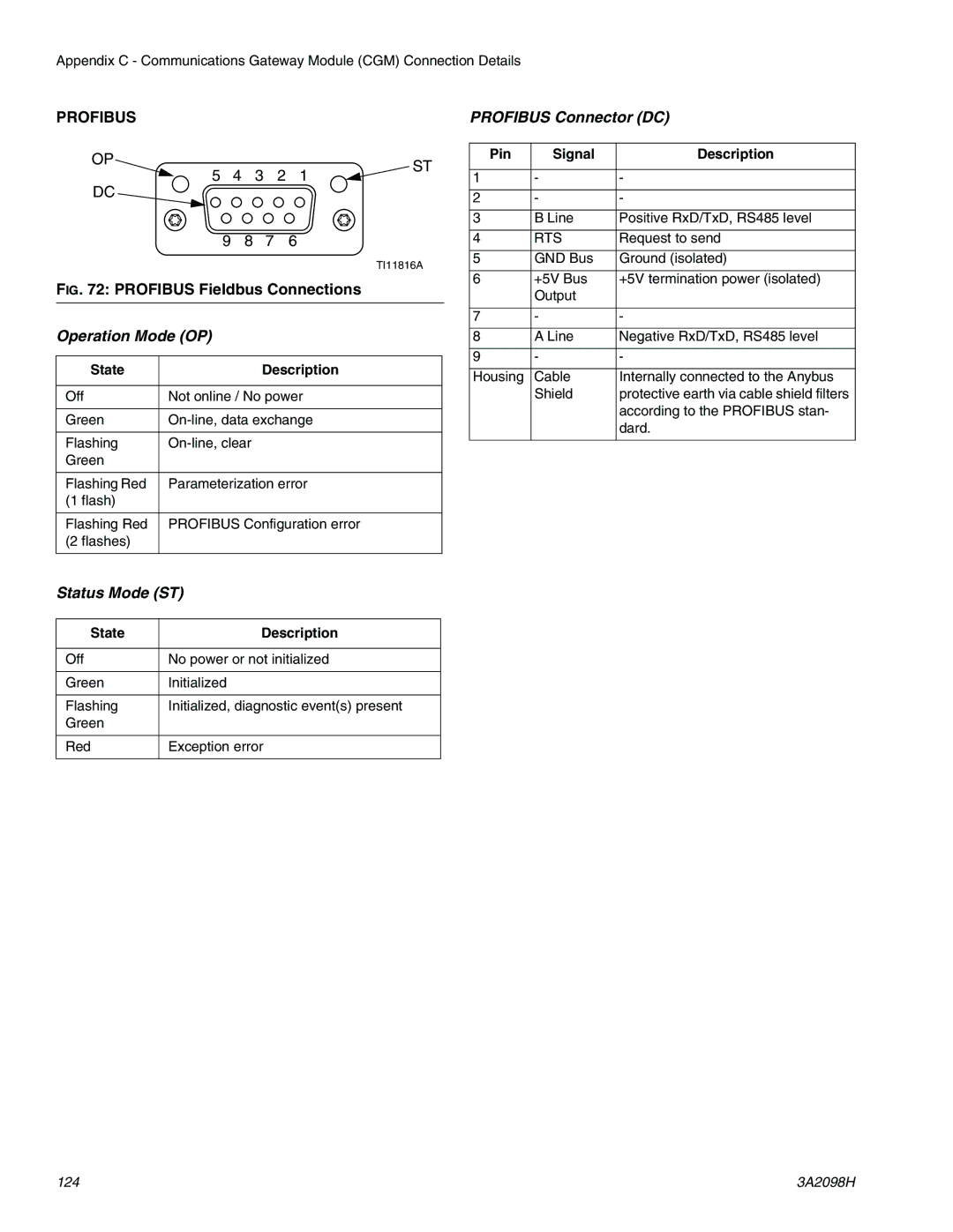
Profibus Fieldbus Connections
RTS
Automation Inputs signals from PCF
See Appendix D I/O Signal Descriptions on
CGM I/O Data Map
Input Byte Bit Description Zone
See CGM Command Interface on
Automation Outputs signals to PCF
Output Byte Bit Description Zone
O96 Command Value O97 O98
3A2098H 129
Read
CGM Command Interface
Examples
Command Interface Timing Diagram
Command Interface Read Operation
Fluid Plate/Swirl Identification Commands
Fluid Plate Commands
3A2098H 133
GalUk ###### Ume Liters Mass ###### Lb, ###### kg
3A2098H 135
Swirl Commands
Output Bits Read or 264-275 Description Gateway Units Write
Unit s String Definition
Units Definitions
Strxy
Appendix D I/O Signal Descriptions
Automation Inputs
Automation Outputs
Control Center Assembly Technical Data
Technical Data
100 240 Vac Assemblies Vdc Assembly
Swirl Dispenser Technical Data
Fluid Plate Assembly Technical Data
Cartridge Regulator Mastic Regulator
Graco Information
Graco Standard Warranty
Graco Headquarters Minneapolis