Hp LaserJet
Page
Service
Copyright Information
Q2431-90912
Table of contents
Printer operation
Removing and replacing parts
Troubleshooting
Index
Viii Table of contents Q2431-90912
List of figures
List of figures Q2431-90912
Q2431-90912 List of figures
Xii List of figures Q2431-90912
Q2431-90912 List of figures
Xiv List of figures Q2431-90912
List of tables
Xvi List of tables Q2431-90912
Q2431-90912 List of tables
Xviii List of tables Q2431-90912
Printer description
Contents
Printer description Q2431-90912
Product configurations
Printer configurations
Sample model and serial number label
Model and serial numbers
Site requirements
Printer specifications
Printer physical dimensions
Physical dimensions
Printer weights
Printer weights without print cartridge
Off
Circuit requirements HP LaserJet 4200 series
General specifications Description HP LaserJet
HP LaserJet 4300 series
Acoustic ratings
Purchasing a large quantity
Paper specifications
B5 ISO
Supported sizes and weights of media
Tray 1 Media specifications
Envelope feeder accessory Size Dimensions
Duplex accessory media specifications Size Dimensions Weight
Stacker and stapler/stacker do not support card stock
Symptom Problem with paper Solution
Guidelines for using paper
Supported types of media
Submenu on
Paper weight equivalents
Paper weight equivalence table
Overhead transparencies
Labels
Envelope construction
Envelopes
Envelopes with double-side-seams
Envelopes with adhesive strips or flaps
Envelope margins
Card stock and heavy paper
Envelope storage
Card stock construction
Types of print media to avoid
Print cartridge and toner safety
Safety information
Laser safety
Laser safety statement U.S
EMI statement Korea Vcci statement Japan
Luokan 1 laserlaite Klass 1 Laser Apparat
Laser statement Finland
Varoitus
Varning
FCC regulations
Regulatory information
Environmental product stewardship program
Material restrictions
Material Safety Data Sheet For more information
Returns Non-U.S. returns
Declaration of Conformity
Declarations of Conformity
Canadian DOC regulations
Service approach
Parts and supplies
Service approach
Ordering information Related documentation and software
Support
HP-authorized resellers and support
HP service agreements
HP PartnerCare
Africa and Middle East
Worldwide service and support offices
Refilled print cartridges
Print-cartridge information
Recycling print cartridges
Returns
HP Product Duration of Warranty
Hewlett-Packard limited warranty statement
Limited warranty for toner cartridge life
Service approach Q2431-90912
Printer operation
Control-panel layout
Using the control panel
Control-panel lights
Control-panel lights Light Indication
Control-panel buttons
Using the printer Help system
Control-panel buttons Button Function
Setting the control-panel display language
Settings and defaults
Settings and defaults
Setting or default Explanation
Overview
Control-panel menus
Printing and changing control-panel menus
To print a control-panel menu map
To change a control-panel setting
Information menu
Retrieve Job menu
Retrieve job menu Values Explanation
Information menu Explanation
Paper-handling menu Values Explanation
Paper Handling menu
Tray N Type ANY
Printing submenu
Configure Device menu
Printing submenu Values Explanation
PCL submenu Values Explanation
PCL sub-submenu a submenu in the printing submenu
Print quality submenu Values Explanation
Print Quality submenu
Lines on page 321 and Blurred print on
321 and Blurred print on page 321 . HP
Use the Resolution Enhancement technology REt
System setup submenu Values Explanation
System Setup submenu
Auto Continue to on
Stapler stacker submenu Values Explanation
Stapler/stacker submenu
O submenu Values Explanation
Submenu
Printer maintenance
Location of the transfer roller do not touch
Cleaning the printer and accessories
Cleaning the printer Component Cleaning method/notes
Cleaning the fuser
To run the cleaning page manually
Running the cleaning page manually
Cleaning spilled toner
Running the cleaning page automatically
To run the cleaning page automatically
Resetting the maintenance-kit counter
Performing preventative maintenance
Maintenance kit part numbers Part name Part number
Expected life of components
Removing and replacing the stapler unit
Maintaining the stapler unit
To remove and replace the stapler unit
Replacing the stapler unit 2
To load staples
Loading staples
Downloading a remote firmware update
Printer maintenance Q2431-90912
Theory of operation
Theory of operation Q2431-90912
Basic operation of the printer
Introduction
Printer operating sequence
Pickup and feed system overview
Control system overview
Laser/scanner system overview
Image formation system overview
DC controller PCA
General descriptions
Motor
Motor and fan control
Fan
Fuser-control circuit
Power supply
Fuser over-temperature protection circuit block diagram
Fuser over-temperature protection
High-voltage circuit
High-voltage circuit block diagram
Low-voltage circuit
Low-voltage circuit block diagram
Toner detection
Overcurrent/overvoltage protection
Cartridge detection
Cartridge memory
Laser/scanner assembly
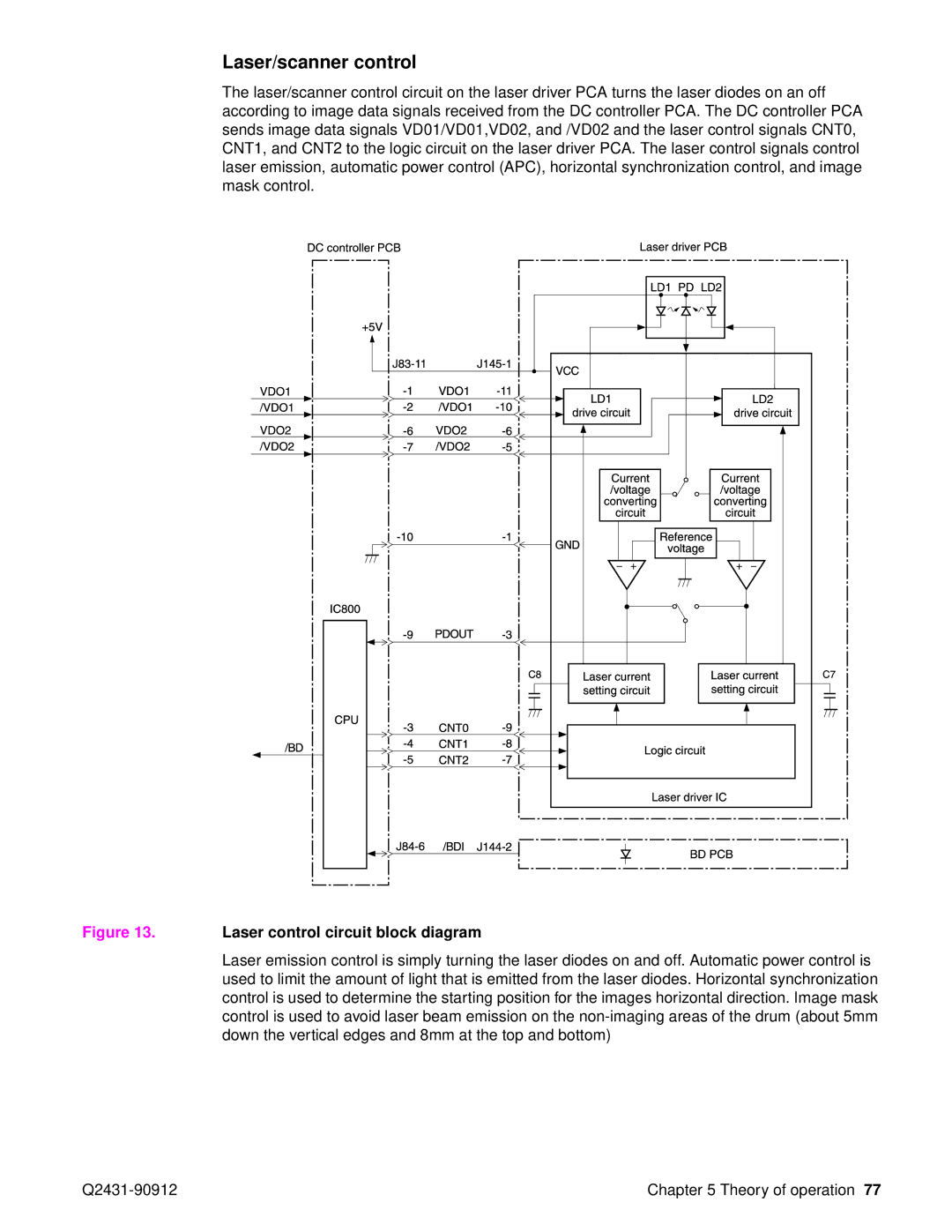
Laser/scanner assembly
Laser/scanner control
Laser control circuit block diagram
Paper pickup system
Printer paper pickup and feed block diagram
Paper pickup and feed block
Paper pickup/feed and fuser/delivery block diagram
Printing from tray
Tray 1 timing diagrams
Q2431-90912 Theory of operation
Tray 1 pickup
Tray 2 timing diagrams
Tray 2, 500-, 1,500-sheet feeder media size detection
No cassette installed
Multiple feed prevention
Lifter-driver operation
Correcting skewed media pages
Media skew prevention
Fixing/delivery block
Printer jam detection
Printer pickup delay jam from tray
Printer pickup stationary jam
Printer delivery wrap jam when feeding non-regular media
Printer delivery wrap jam when feeding regular media
Printer delivery delay jam
Printer residual media jam
Printer door open jam
Sheet feeder pickup and feeding
Printing from the 500-sheet feeder
Sheet feeder pickup and feed diagram
Printing from the 1,500-sheet feeder
500-sheet feeder I/O block diagram
500-sheet feeder pickup and feed diagram
500-sheet feeder lifting mechanism
Sheet feeder lifting mechanism
Envelope feeder
Envelope feeder I/O block diagram
Envelope feeder pickup and feeding
Envelope feeder pickup and feed diagram
Envelope feeder jam detection
Envelope feeder pickup delay jam
Envelope feeder pickup stationary jam
Duplexer
Duplexer I/O block diagram
Reversing and duplexer pickup
Duplexer pickup and reversing diagram
Duplexer jam detection
Stacker and stapler/stacker paper path
Stacker and stapler/stacker
Power-on sequence for the stacker and stapler/stacker
Stacker
Stacker driver PCA block diagram
Stacker feed and delivery
Switch
Stacker components Component Purpose
Solenoid
Stacker feed jam
Stacker jam detection
Stacker feed stationary jam
Stacker residual media jam
Stapler/stacker
Stapler/stacker driver PCA block diagram
Stapler/stacker components Component Purpose
Stapler/stacker feed and delivery
Stapler/stacker motors, solenoids, and sensors block diagram
Staple mode feed and delivery diagram 1
Staple mode feed and delivery
Staple mode feed and delivery diagram 2
Staple mode feed and delivery diagram 4
Staple mode feed and delivery diagram 6
Stapler unit
Stapler unit I/O block diagram
Stapler unit
Stapler unit operation
Front view
Staple operation 3
Staple operation 2
Staple level detection
Stack mode feed and delivery
Stapler/stacker feed jam
Stapler/stacker jam detection
Stapler/stacker feed stationary jam
Stapler/stacker delivery jam
Image-formation system
Image formation block diagram
Primary charging
Electrostatic latent-image formation
Writing the image to the photosensitive drum
Writing the image
Developing the image
Developing the image
Transferring the image
Transferring the image
Fusing the image
Q2431-90912 Theory of operation
Print cartridge memory chip
Print cartridge memory chip
Resolution Enhancement technology
PowerSave
Formatter system
Input/output
EconoMode
Printer memory
Control panel
PJL overview
Removing and replacing parts
Page
Before performing service
Removal and replacement strategy
After completing service
Required tools
Screw measurement guide
Screws used in the printer
Phillips machine screw with captive star washer
Phillips screw with self-tapping threads
Parts-removal tree
Access to the transfer assembly and to the registration
Location of printer, input trays, and cabinet wheel locks
Printer input tray, and cabinet wheel locks
Print cartridge
User-replaceable parts
Print cartridge 1
Open the control-panel door and tray
Transfer roller
Tray 1 pickup roller 1
Tray 1 pickup roller
Tray 1 separation pad
Tray 1 separation pad
Tray 2 feed rollers 2
Tray 2 feed rollers
Tray 2 feed rollers 3
Covers, tray 1, and the rear output bin
Accessory covers and the tray 2 extension door
Accessory covers 3
Formatter cover
Top cover 1
Top cover
Top cover 4
Top cover 3
Top cover 5
Right-side cover 1
Right-side cover
Right-side cover 3
Left-side cover 1
Left-side cover
Tray 1 1
Tray
Slide the tray 1 door to the right and remove it
Tray 1 3
Slide the paper guide to the left to remove it
Tray 1 5
Tray 1 6
Rear output bin 1
Rear output bin
Control-panel overlay
Control-panel display
Control-panel assembly 1
Control-panel assembly
Control-panel assembly 2
Control-panel assembly 4
Firmware Dimm
Internal components
Firmware Dimm
Formatter assembly
Formatter assembly
Fuser
Output delivery assembly rear view, formatter side 1
Output delivery assembly
Output delivery assembly 2
Duplexing pendulum assembly 1 o
Duplexing pendulum assembly
Duplexing pendulum assembly 2
Tray 2 media-size sensor 1
Tray 2 media-size sensor
Main cooling fan 1
Main cooling fan left side
Main cooling fan 3
Cooling fan HP LaserJet 4300 series only 1
Cooling fan right side HP LaserJet 4300 series printer only
Cooling fan HP LaserJet 4300 series only 3
Cooling fan HP LaserJet 4300 series only 5
Laser/scanner 1
Laser/scanner 4
Laser/scanner 3
Print-cartridge motor HP LaserJet 4300 series only 1
Print-cartridge motor HP LaserJet 4300 series printer only
Print-cartridge motor HP Laserjet 4300 series only 1
Main motor 1
Main motor
Remove it
Main motor 3
Tray 2 lifter-drive assembly 1
Tray 2 lifter-drive assembly
Tray 2 lifter-drive assembly 2
DC controller PCA 1
DC controller PCA 2
Paper-pickup assembly 1
Paper-pickup assembly
Paper-pickup assembly 3
Paper-pickup assembly 5
Main drive assembly 1
Main drive assembly
Main drive assembly 2
Power supply right side 1
Power supply 2
Power supply tray 2 cavity 4
Paper-feed belt assembly 1
Paper-feed belt assembly
Tray 1 pickup assembly 1
Tray 1 paper-pickup assembly
Tray 1 pickup assembly 2
Tray 1 pickup assembly 4
Paper feed assembly 1
Paper feed assembly
Paper-feed assembly 2
Reinstall note Hint
Registration assembly 1
Registration assembly
Registration assembly 3
Transfer assembly 1
Transfer assembly
Transfer assembly left rear view 2
Transfer assembly 3
Transfer assembly 5
Sheet feeder assembly
Accessories
Sheet feed rollers
Sheet feeder right-side cover
Sheet feeder right-side cover 2
Sheet feeder right-side cover 4
Sheet feeder control PCA
Sheet feeder control PCA
Sheet feeder media-size sensor 1
Sheet feeder media-size sensor
Sheet feeder lifter-drive assembly 1
Sheet feeder lifter-drive assembly
Sheet feeder paper-pickup drive assembly 1
Sheet feeder paper-pickup drive assembly
Sheet feeder paper-pickup drive assembly 3
Sheet feeder paper-pickup drive assembly 5
Sheet feeder paper-pickup drive assembly 7
Sheet feeder separation roller
Sheet feeder feed rollers
500-sheet feeder door 1
Sheet feeder door
Sheet feeder door 3
500-sheet feeder rear cover 1
Sheet feeder rear cover
500-sheet feeder right-side cover 1
500-sheet feeder right-side cover 3
500-sheet feeder control PCA 1
500-sheet feeder media-size sensor
500-sheet feeder lifter-drive assembly 1
500-sheet feeder lifter-drive assembly 2
500-sheet feeder lifter-drive assembly 4
500-sheet feeder paper-pickup drive assembly
Removing and replacing parts Q2431-90912
Troubleshooting
Troubleshooting Q2431-90912
Q2431-90912 Troubleshooting
Introduction
Troubleshooting process
Initial troubleshooting checklist
Initial troubleshooting checklist Miscellaneous
Troubleshooting flowchart 1
Troubleshooting flowchart
Troubleshooting flowchart 2
Overview
Power-on checks
Power-on defect or blank display Problem Action
Power-on defect or blank display
Information pages
Troubleshooting tools
Sample menu map
Menu map
Configuration
Configuration
Supplies status
Supplies status
Embedded Web server
Gaining access to the embedded Web server
Information tab
Settings tab
Networking tab
Other links
Printer Status and Alerts software
To view status messages and information
To select status messages
Resets submenu
Using control-panel menus
Resets submenu Values Explanation
Information see System Setup submenu on
Diagnostics menu Values Explanation
Diagnostics menu
For the HP LaserJet 4300 product
Service menu service PIN codes
Restoring the Service ID
Service ID
Converting the Service ID to an actual date
Cold reset
Printer resets and power-on modes
To perform a cold reset
Nvram initialization
Hard-disk initialization
Power-on bypass
To initialize the hard disk
Skip disk load
Self test
Engine test
Test pages
Formatter test
EIO troubleshooting
Interface troubleshooting
Communications checks
Computer direct connect parallel test
Jetdirect
Jetdirect
Error messages
Display-message troubleshooting
Critical-error messages
Status messages
Alphabetical printer messages Message Description Action
Alphabetical printer messages
See DC controller PCA on
Top cover is open or the top Press the H ELP Button for
Firmware Dimm on
Dimm on
Switches and sensors on
See Configuration page on
See Power supply on
336 , 500 -sheet feeder
Fuser on
Configuration page on
See Fuser on
On page 241 to see if
Stacker or stapler/stacker LED Blinks in amber
Sheet feeder media
Size detection on
Printer has detected that an If the print cartridge appears
LED blinks in amber
Stacker or stapler/stacker
Stacker or stapler/stacker LED
See Firmware Dimm on
Power supply on
Control PCA on
Sheet feeder
See 1,500-sheet feeder
Amber this error applies to
Error applies to the stapler/stacker
Stapler/stacker LED is
Only
On page 340, or
Tray was installed with Use the control panel to
Configuration of tray XX. The tray Press the S Elect
Select the Paper Handling
Numerical printer messages Message Description Action
Numerical printer messages
Cartridge on
See Paper-path
Assembly sensor flag on
Install the paper-feed
See Printer switches
Sheet feeder switches
Correctly install
Printer switches
Paper-feed assembly sensor
Location of printer switches
336 and Fuser on
See Location of printer
Removing and replacing
JAM in Output Device
Tray 2 feed rollers on
Functions to OFF
Description
Drivers and Software . Check
Replace the Dimm or
ZZ Error Number
Scanner assembly on
Formatter assembly on
Main fan error F1
Cartridge fan error F2
Power supply
Air temperature sensor
DC controller
Sensor. See Main cooling
Or 59.4 EP Motor failure
59.00, 59.10, 59.20 Motor
LJ 4300 only
Feeder lifter-drive assembly
Assembly. See Tray 2 lifter
Print-cartridge motor
On page 209 or 1,500-sheet
Is off
60.4
Is continuously illuminated
Settings and defaults on
Amber
Stapler unit on
Initialize the hard disk on
Initialize Nvram on
Critical hardware error has Turn the printer off and then
Jam locations
Paper-path troubleshooting
To disable the paper-jam recovery
Paper-jam recovery
Avoiding paper jams
Common causes of paper jams Cause Solution
Persistent jams
Basic troubleshooting for persistent jams
Data collection
Paper-path checklist
General paper-path troubleshooting
To perform a paper- test
Paper-path test
Causes of tray 2 jams Solution
Causes of tray 1 jams Solution
Tray 1 paper-pickup assembly on
Drive assembly on page 179 and/or Printer
Jams in tray 3 and/or tray
Causes of tray 3 and or tray 4 jams Solution
Causes of duplex path jams Solution
Causes of paper-path jams Solution
Drive assembly on
Jams in the paper path
Causes for multiple pages feeding Solution
Media transport problems
Cause Solution
Multiple pages feed
Registration assembly on
Causes for skewed paper Solution
Paper is skewed
Print quality problems associated with media
Image-formation troubleshooting
Print quality problems associated with jams
Print quality problems associated with the environment
Overhead transparency defects
HP paper specification
Does the problem repeat on the page?
Image defects
Image quality
EconoMode
Check the print cartridge
Drum rotation functional check
Half self-test functional check
Print quality image defects
Image defect tables
Print quality image defects
Light print entire Possible cause Recommended action
Light print partial Possible cause Recommended actions
Dots in the paper path direction
Specks or dots Possible cause Recommended action
Have this problem because they are not
Might cause problems if the paper is
Cartridge Wrong toner density setting
Wrong fuser setting for media type
Horizontal lines opposite the paper path direction
Grey background Possible cause Recommended actions
Distorted images
Repeating defects and repeating images
Curl or wave Possible cause Recommended actions
Skew Possible cause Recommended actions
Creases Possible cause Recommended actions
White lines opposite the paper path
White spots on black Possible cause Recommended actions
Line detail setting is turned off
Scattered lines Possible cause Recommended actions
Blurred print Possible cause Recommended actions
Black
Replace the laser/scanner assembly. See Laser/scanner
Blank or white Possible cause Recommended actions
Dark print
Repetitive defect ruler
Repetitive defects troubleshooting
Initial checks
Troubleshooting the stacker and the stapler/stacker
Stacker and stapler/stacker paper path
Jam errors
Stacker paper path test
Delivery area Printer connection area
Damaged
Stapler/stacker paper path test
Q2431-90912 Troubleshooting
Malfunction errors
Paper transport errors
Paper transport error troubleshooting
Component errors
Main printer parts
Printer component locations
Location of main printer parts 2
Location of main printer parts 3
Location of main printer parts 4
Location of printer switches and sensors
Printer switches and sensors
Location of printer motors and fans
Printer motors and fans
Location of printer PCAs
Printer PCAs
Sheet feeder main parts
Accessory component locations
Sheet feeder switches, sensors, solenoids, and PCAs
Location of 1,500-sheet paper feeder main parts 1
Location of 1,500-sheet paper feeder main parts 2
Sheet feeder switches, sensors, solenoids, and PCAs
Location of the stapler/stacker stapler unit
Stapler/stacker stapler assembly
Stacker and stapler/stacker switches and sensors
Stacker and stapler/stacker motors and solenoids
Location of the stacker and stapler/stacker PCAs
Stacker and stapler/stacker PCAs
HP LaserJet 4200 wiring diagram
Printer and accessory wiring diagrams
HP LaserJet 4300 wiring diagram
Sheet feeder wiring diagram
500-sheet feeder wiring diagram
Duplex accessory wiring diagram
Envelope feeder accessory wiring diagram
Stacker accessory wiring diagram
Stapler/stacker accessory wiring diagram
DC controller top
DC controller block diagram
HP LaserJet 4200 general timing diagram
General timing diagrams
HP LaserJet 4300 general timing diagram
Stapler/stacker timing diagram
Troubleshooting Q2431-90912
Parts and diagrams
Ordering information
Ordering parts, supplies, and getting support
HP-authorized resellers and support
Accessories and supplies
Cables and interfaces Part number Exchange number
Memory, fonts, and mass storage Part number Exchange number
Part number Exchange number
Printer maintenance kit
Documentation Part number Description or use
How to use the parts lists and diagrams
External covers and panels
Parts diagrams and lists
External covers and panels Part number Description Reference
Main assemblies 1
Main assemblies 1 Part number Description Reference
Main assemblies 2
Main assemblies 2 Part number Description Reference
Main assemblies 3
Main assemblies 3 Part number Description Reference
Right-side assemblies Part number Description Reference
110-127v 220-240v
Main drive assembly Part number Description Reference
Paper-pickup assembly Part number Description Reference
RM1-0002-000CN Duplexing pendulum assembly
RM1-0033-000CN Lifter-drive assembly, tray
Paper pickup assembly Part number Description Reference
Paper-feed assembly Part number Description Reference
Registration assembly Part number Description Reference
Tray 1 assembly Part number Description Reference
Output delivery assembly Part number Description Reference
Transfer assembly Part number Description Reference
Transfer assembly
Fuser Parts and diagrams Q2431-90912
Fuser Part number Description Reference
Parts and diagrams Q2431-90912
Q2431-90912 Parts and diagrams
Sheet feeder main assemblies 2
Q2431-90912 Parts and diagrams
RM1-0056-000CN Paper-pickup assembly 500-sheet feeder
RM1-0208-000CN Lifter-driver assembly 500-sheet feeder
Sheet tray Part number Description Reference
Sheet tray
Q2431-90912 Parts and diagrams
500-sheet feeder main assemblies
Paper size sensing assembly outside, 1,500-sheet feeder
Parts and diagrams Q2431-90912
RM1-0287-000CN Lifter-drive assembly, 1,500-sheet feeder
Parts and diagrams Q2431-90912
Q2431-90912 Parts and diagrams
Parts and diagrams Q2431-90912
Alphabetical pars list Part number Description Reference
Alphabetical parts list
Alphabetical pars list Part number Description Reference
Paper size sensing assembly outside, 1,500-sheet feeder
Alphabetical pars list Part number Description Reference
Numerical pars list Part number Description Reference
Numerical parts list
Numerical pars list Part number Description Reference
Numerical pars list Part number Description Reference
Paper size sensing assembly outside, 1,500-sheet feeder
Index
Index Q2431-90912
Cassettes. See trays CD-ROM, software
Index Q2431-90912
EIO
Index Q2431-90912
See also support troubleshooting Help button 36
LED PCA
Q2431-90912 Index
Index Q2431-90912
Q2431-90912 Index
See also bins
Q2431-90912 Index
Index Q2431-90912
LED PCA
TCP/IP
See also trays
See also messages troubleshooting problem areas
Page
Q2431-90912