5016-001
5016-001
United States Government Restricted Rights
Table of Contents
Erase Lamp Service Check Fuser Cold Service Check
5016-001
Developer Drive Motor Assembly Removal
Vii
Index
Laser Notices
Laser Notice
Laser
Avis relatif à l’utilisation de laser
Avvertenze sui prodotti laser
Avisos sobre el lá ser
Declaraçã o sobre Laser
Laserinformatie
Lasermeddelelse
Huomautus laserlaitteesta
Luokan 1 Laserlaite
Laser-notis
Laser-melding
Avís sobre el Là ser
Japanese Laser Notice Chinese Laser Notice
Korean Laser Notice
Safety Information
Norme di sicurezza Italian
Pautas de Seguridad Spanish
Informació de Seguretat Catalàn
Korean
5016-001
General Information
Models
Standard Features
5016-001 printer is available in the following models
Unix
32MB Sdram
From an IrDA-compatible workstation
Maintenance Approach
Tools Required For Service
Options
Ipds SCS
Operational Theory
Interlock Mechanism
Sheet Bypass Paper Feed Unit
Double feed prevention
5016-001 Detecting paper present
Paper Feed Unit
Operation of the paper feed unit tray
Detecting the paper
Detecting paper level
5016-001 Detecting paper size
Second Paper Feed Unit Optional Paper Trays
Construction of the Second paper feed option
5016-001 Operation of the Second paper feed unit
5016-001 Detecting the paper
5016-001 Detecting paper size
Drive Block
Operation of the Drive Block
Operation of transferring from the OPC to the transfer belt
Contact Cam
Operation of transferring from the belt to the paper
Manual resetting
Coupling Unit
5016-001
Carriage Unit
Rotation and stopping operation of the carriage
Detecting the carriage
Detecting the carriage home position
Toner Cartridge Unit
Detecting a new cartridge
5016-001 Detecting toner level
Intermediate Transfer Unit
Function of the intermediate transfer unit
5016-001
Page
Fuser/Paper Exit Unit
Operation of the fuser and paper exit
Detecting New Cleaning Unit
Detecting the cleaning unit in the Fuser Assembly
Duplex Unit Option
One side print
5016-001 Two sided print
5016-001
5016-001 When the setting is four pages
Page
5016-001 Exit of the one sided print
5016-001 Detecting the paper exit tray open/close
Detecting the duplex upper unit open/close
5016-001 Gate claw operation, when print exits
5016-001 Storage of the paper in the duplex unit
5016-001 Operation of the motor
5016-001
5016-001
5016-001 Skew Correction
Acronyms
Diagnostic Information
Start
Service Error Codes
Error Code Action
Go to the Printhead Service Check on
Engine Board Assembly Removal on
Coupling Unit Service Check on
Contact Cam System Service Check on
User Status Messages
Message Status Action
Until the Job Menu is
Unlocking Menus
Restoring all print settings to
Restore EP Factory Defaults on
5016-001
User Attendance Messages
Cancel Job appears on
PIN
Delete All Jobs
5016-001
Second line. Press Select
Displayed. Press Menu
5016-001
Attached
Processing the current print
Your Setup Guide for
Format Disk from
Saver, Busy and Waiting
Displays on the operator
Displays 230 Paper Jam
Symptom Tables
Base Printer Symptom Table
Covers Interlock Symptom Table
Duplex Unit Symptom Table
Operator Panel Symptom Table
Paper Feed Symptom Table
Paper Tray Options Symptom Table
Power Symptom Table
Print Quality Symptom Table
Go to the Poor Color
Service Checks
Bypass Tray Multipurpose Tray Service Check
Base Printer Service Checks
Multipurpose Tray Symptom Chart
Media does not feed from MPT, 250 paper jam message displays
Transparencies do not feed, or feed improperly from the MPT
Labels do not feed, or feed improperly from the MPT
Card stock does not feed properly from the MPT
Carriage Unit Service Check
Double feeding from MPT tray
If the voltage on pin 2 is incorrect, check cable
5016-001
Coupling Unit Service Check
Service Engine Error Motor turns
Service Engine error
Cover Interlock Service Check
If correct, check the voltage on switch terminal
Fuser Error displays
If incorrect, go to the Printhead Service Check
Developer/Paper Feed Motor Service Check
Service Error Code 911 displayed
Feed Motor Cable
Erase Lamp Service Check
Fuser Cold Service Check
5016-001 921 Error codes
Fuser Drive and Contact Cam System Service Check
Fuser drive system is not operating properly
Cam turns from approximately 0 V to +5 V dc
Continuity of the CRF cable to the cam
Fuser Hot Service Check
Cold Approximately 150k to 250k ohms
High Voltage Leakage Detect Service Check
Error Code
Hvps
ITM Drive Service Check
5016-001
Main Fan Service Check
Pin 3 Red
New Toner Cartridge Detection Service Check
Operator Panel Service Check
Operator Panel Buttons Service Check
OPC Drive Symptom Chart
OPC Drive Service Check
Error Code 910 displays
Paper Exit Sensor Service Check
Paper Feed Service Check
Paper Feed Symptom Table
Check the voltages on the inline CRF cable
Go to the Paper Exit Sensor Service Check
Parallel Port Service Check
Fuser assembly available
Power Service Check
5016-001
CN401
5016-001
Go to the 250/250 Dual Paper Tray Service
Printhead Service Check
933 Error Codes are not used
935 Error Codes
Print Quality Service Checks
Print Quality Initial Service Check
All Black or Color Page Service Check
FRU
All Blank Page Service Check
ITM
Background Service Check
Go to the Erase Lamp Service Check on
Black, Color Lines or Bands Service Check
Black or Color Spots Service Check
Developer Drive System Service Check
Evenly Spaced Horizontal Lines/Marks Service Check
Line spacing
Foggy Background Service Check
Low Image Density Service Check
Offset Print Service Check
Poor Color Reproduction Service Check
Random Marks Service Check
Residual Image Service Check
Skew Service Check
Toner on Backside of Page Service Check
Uneven Print Density Service Check
White Lines or Bands Service Check
Be sure the mounting screws in the Hvps are
White Spots Service Check
White/Black Lines Service Check
Serial Port Service Check
Toner Level Detect Service Check
Toner Low/Empty Sensor Service Check
Transfer Roll Service Check
Tray 1 Integrated Tray Service Check
Tray 1 Symptom Chart
It is difficult to remove tray
Detect Sensor
Paper Feed Unit Clutch
5016-001
5016-001
Media double feeds from tray
Flash Memory Options Service Check
Options Service Checks
Dram Memory Options Service Check
Hard Disk Option Service Check
Network Card Option Service Check
250/250 Dual Paper Tray Service Check
Error Code 976 Network Card X X=Network card 1, 2, or
Error Code 977 Network Card
250/250 Paper Tray Symptom Table
FRU
Tray x is correctly installed and Insert Tray x displays
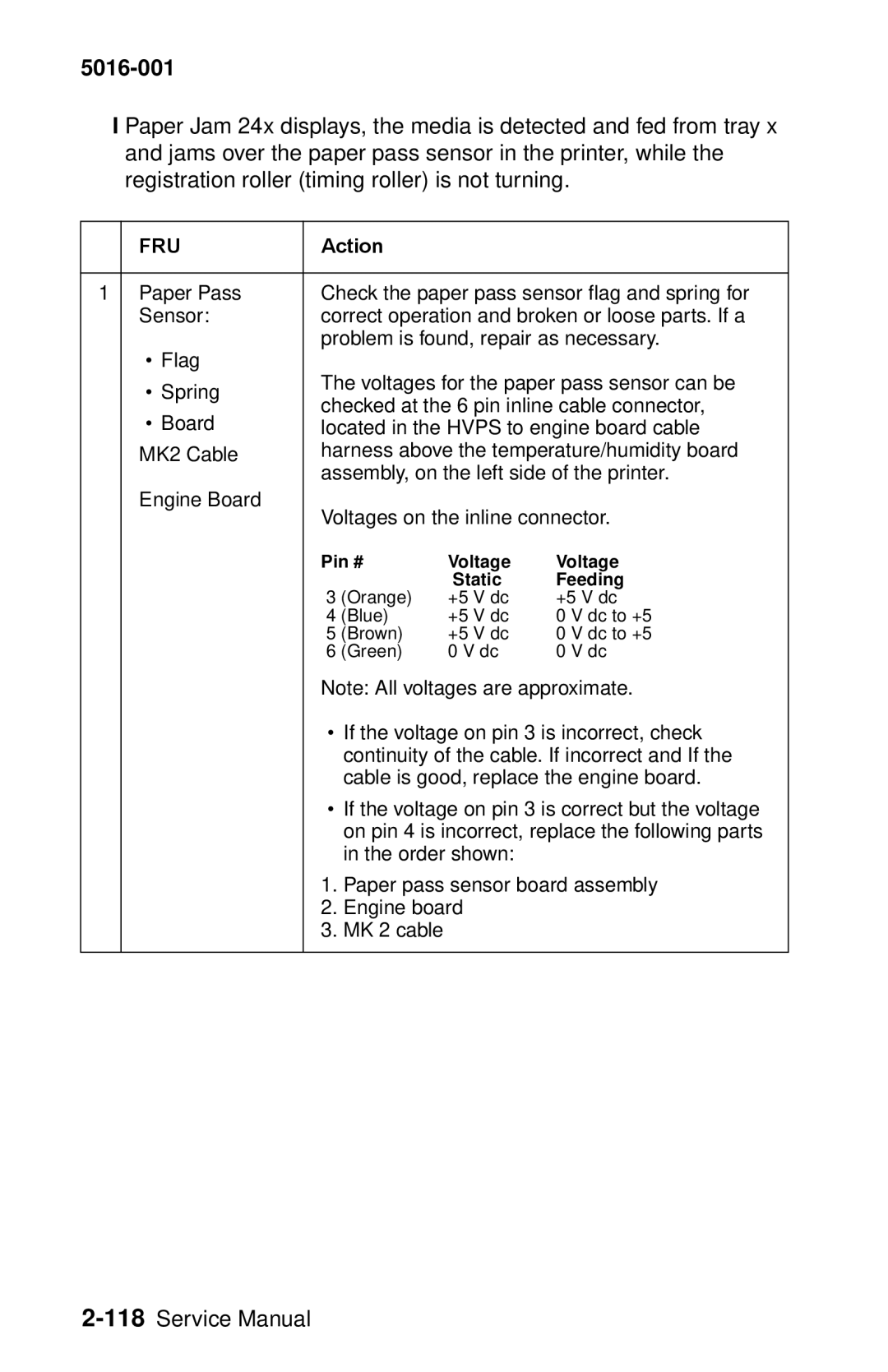
Paper Jam 24x displays and no paper is fed from tray
CL3
5016-001
If the static voltages are correct and the sensor
Shaft Middle Roller Drive Gear
Orange +5 V dc Blue Dc to +5 Brown Green
5016-001
Paper size in tray x is not detected
Paper level in tray x is not detected
Paper Jam Error Messages Duplex
Duplex Unit Option Service Check
Paper Jam Error Messages Printer
5016-001 Duplex Symptom Chart
Paper Jam error message displays
Duplex option is not recognized
Error message displays, printer does not compete POR
Duplex Lvps
Gate Claw
ADL, ADT
Signal Static
If the voltage on pin 6 does not change when
If the voltage on pin 11 is incorrect, replace
Lower
Transfer Roll
Transfer Drive
Pulley Transfer Gears Timing Belt
Unit S3
Paper Jam displays. The printer does not complete POR
Duplex option printed page is skewed
To Skew Correction on
5016-001
Print Quality Test Pages
Paper Jam Sequence
Paper Jam 202 Duplex Installed Go to the Duplex Unit
Paper Jam
Diagnostics Menu Structure
Disabling Download Emulations
Diagnostic Mode
5016-001
Print Registration
5016-001
Print Tests
Print Quality Test Pages
Hardware Tests
LCD Test
Button Test
Following Hardware Tests can be selected from this menu
Parallel Wrap Test
ROM Memory Test
Sdram Memory Test
Serial Wrap Test
Quick Test
Duplex Tests
Duplex Feed
Device Tests
Quick Disk Test
Disk Test/Clean
Flash Test
Printer Setup
Setting the Page Count
Viewing the Permanent Page Count
Serial Number
Setting Configuration ID
Laser Power
Parallel Strobe Adjustment
Error Log
Viewing the Error Log
Clearing the Error Log
Restore EP Factory Defaults
Exiting Diagnostic Mode
5016-001
Repair Information
Handling ESD-Sensitive Parts
Cover Removals
Cartridge Cover Removal
Front Cover Removal
Fuser Cover Removal
Left Side Cover Removal
Top Cover Removal
Right Side Cover Removal
Top Small Cover Removal
Right Side Removals
Carriage Drive Motor Removal
Developer Drive Motor Assembly Removal
Coupling Drive Motor Removal
Fuser Drive Motor Removal
OPC Drive Motor Removal
Cam Sensor Removal
Lvps Assembly Removal
5016-001
Main Fan Removal
Main Fan Mounting Bracket Removal
Motor Mounting Stay C Assembly Removal
OPC Coupling Drive Block Assembly Removal
Solenoid Removal
Left Side Removals
Grid Block 1 Assembly Removal
Grid Block 2 Assembly Removal
Micro Switch Removal
Cover Interlock Switch Removal
Cable Cover 3 Removal
Engine Board Assembly Removal
Controller Board Assembly Removal
Electronics Removals
Hvps Board Assembly Removal
On/Off Coupling Sensor Board Removal
Interconnect Board Assembly Removal
Paper Sensor Board
Waste Toner Board Assembly Removal
Resist Sensor Board Removal
Fuser Unit
Fuser Unit Removal
Fuser Lamp Removal
Thermistor and Thermostat Removal
Paper Feed Block Assembly Removal
Main Body
Paper Sensor Board Removal
Printhead Removal
OPC Coupling Drive Block Assembly Removal on
Print Cartridge Carousel Removal
Carriage Home Position Sensor Removal
Registration Roll Removal
5016-001
Connector Locations
Engine Board
Engine Board Connector
5016-001 Engine Board Connections
Erase Lamp Board
Lvps Low Voltage Power Supply
Tray 1 Sensor Board
Tray 1 Registration Sensor Board
Waste Toner Sensor Board
Belt Position Sensor Board
Connector Locations for Options
2nd Paper Option 250/250 Paper Option
Connector
Lvps Internal 2nd Tray Option
Duplex Unit Option
Lvps Internal Automatic Duplex Option
Sensor/Switch Locations
Electrical Components
Symbol Name Function
Detects when the transfer belt is in the home
Printer Circuit Board Locations Fan/Motor Locations
Solenoid/Clutch Locations
250/250 Paper Tray Option
Duplex Option
Cable Connections
Reference
EVL
5016-001
Safety Inspection Guide
Service Precautions
Cleaning Procedures
Lubrication Specifications
5016-001
How To Use The Parts Catalog
Parts Catalog
Assembly 1 Fuser
Assembly
Asm Index Part Number
Assembly 2 Fuser
Asm Part Units Description Index Number
Assembly 2 Cont. Fuser
Assembly
Assembly 3 Transfer
Assembly
Assembly 4 Frames
Assembly
Assembly 5 Frames Left Side
Assembly
Assembly 5 Cont. Frames Left Side
Assembly
Assembly 6 Frames Right Side
Assembly
Assembly 6 Cont. Frames Right Side
12G1123 Stop, Latch, Right 12G1072 Support
Assembly 7 Frames Right Side
Assembly
Assembly 7 Cont. Frames Right Side
Assembly
Assembly 8 Frames Right Side
Assembly
Assembly 9 Carriage Block
Assembly
Assembly 10 Base Frame
Assembly
Assembly 11 Front Cover Assembly
Assembly
Assembly 11 Cont. Front Cover Assembly
Assembly
Assembly 12 Front Cover Assembly
Asm Part Units Description Index Number
Assembly 12 Cont. Front Cover Assembly
Assembly 12
Assembly 13 Feed Unit
Assembly
Assembly 14 Laser Scanner Unit
Assembly
Assembly 14 Cont. Laser Scanner Unit
Assembly 14
Assembly 15 Cassette
PCB
Assembly 16 Upper Covers
Assembly
Assembly 16 Cont. Upper Covers
Assembly
Assembly 17 Covers
Assembly
Assembly 18 Covers / Frame 250 Tray Option
Assembly
Assembly 18 Cont. Covers/Frame 250 Option
Assembly 18
Assembly 19 Middle Roll Unit 250 Tray Option
Assembly
Assembly 20 250/250 Tray Option Lower Unit
Assembly
Assembly 21 Duplex Unit Option
Assembly
Assembly 21 Cont. Duplex Unit Option
Assembly
Assembly 22 Cassette Upper Section
Assembly
Assembly 23 Cassette Rear Section
Assembly
Assembly 24 Cassette Rear Section
Assembly
Assembly 25 Duplex Option Lower Section
Assembly
Assembly 25 Cont. Duplex Lower Section
Assembly
Assembly 26 Duplex Option Lower Section
Assembly
Assembly 27 Duplex Option Lower Section
Assembly
Assembly 28 Cassette Lower Section
Assembly
Assembly 29 Duplex Option Lower Section
Assembly
Assembly 29 Cont. Duplex Option Lower
Assembly
Assembly 30 Miscellaneous
128MB Sdram Dimm
Index
Index
Hvps
Evenly Spaced Horizontal Lines
Part Numbers
5016-001
12G1135 12G1181
5016-001
61,7-67,7-75
35 , 7-39 , 7-61 , 7-71
12G1538 12G1585 13,7-41 12G1539 12G1586
12G1617
5016-001