Multi-Tech Systems MVP-130/130FXS, MVP-410ST/810ST, MVP-2410/3010 manual Pin connectors, 514

Models: MVP-410ST/810ST MVP-130/130FXS MVP-2410/3010

1 559
Download 559 pages 35.93 Kb
Page 514
Image 514

8-Channel Analog Expansion Card

MultiVOIP User Guide


11.Locate the male 60-pin vertical connector near the LED edge of the main circuit card. Check that pins are straight and evenly spaced. If not, then correct for straightness and spacing. Locate the 60-pin female connector on the upgrade circuit card.

12.Set the upgrade circuit card on top of the main circuit card. Align the upgrade card’s 4 pairs of phone-jacks with the 4 pairs of holes in the backplane of the main card. Slide the phone jacks into the holes.

13.Mate the upgrade card’s 60-pin female connector with the main card’s 60- pin male connector.

* *

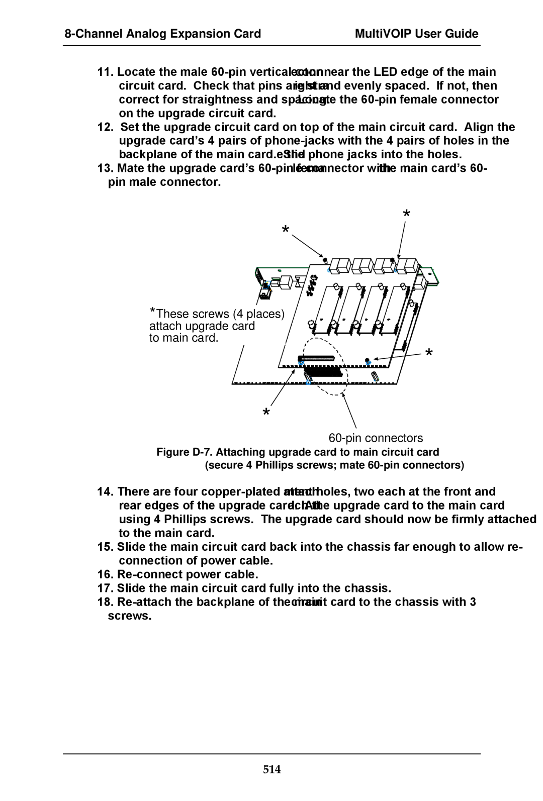
*These screws (4 places) attach upgrade card

to main card.

*

*

60-pin connectors

Figure D-7. Attaching upgrade card to main circuit card (secure 4 Phillips screws; mate 60-pin connectors)

14.There are four copper-plated attachment holes, two each at the front and rear edges of the upgrade card. Attach the upgrade card to the main card using 4 Phillips screws. The upgrade card should now be firmly attached to the main card.

15.Slide the main circuit card back into the chassis far enough to allow re- connection of power cable.

16.Re-connect power cable.

17.Slide the main circuit card fully into the chassis.

18.Re-attach the backplane of the main circuit card to the chassis with 3 screws.

514

Page 514
Image 514
Multi-Tech Systems MVP-130/130FXS, MVP-410ST/810ST, MVP-2410/3010 manual Pin connectors, 514