MultiVOIP
S000249K
User Guide
Contents
Contents MultiVOIP User Guide
MultiVOIP User Guide Contents
Appendix a Expansion Card Installation MVP24-48 & MVP30
Overview
About This Manual
MultiVOIP Product Family
Variable Model/Version Icon
MultiVOIP MVP2410 LEDs
Introduction to TI MultiVOIPs MVP2410 & MVP24-48
Overview MultiVOIP User Guide
MultiVOIP User Guide Overview
Overview MultiVOIP User Guide
MultiVOIP User Guide Overview
MVP2410 LEDs
T1 Front Panel LEDs
LED Name Description
MVP2410 Front Panel LED Definitions
MultiVOIP MVP3010 Chassis
Introduction to EI MultiVOIPs MVP3010 & MVP30-60
MultiVOIP User Guide Overview
Overview MultiVOIP User Guide
MultiVOIP User Guide Overview
Overview MultiVOIP User Guide
MVP3010 LEDs
E1 Front Panel LEDs
MVP3010 Front Panel LED Definitions
E1 LED Descriptions
MVP-410/810 Chassis
MultiVOIP MVP-130/130FXS Chassis
MultiVOIP User Guide Overview
Overview MultiVOIP User Guide
MultiVOIP User Guide Overview
MVP410/810 LEDs
Analog MultiVOIP Front Panel LEDs
10. MVP210 LEDs
Ethernet
Power
Boot
Analog MultiVOIP LED Descriptions
MVP-130/130FXS Front Panel LED Definitions
12 MVP-410ST/810ST Chassis
Introduction to ISDN-BRI MultiVOIPs MVP410ST & MVP810ST
MultiVOIP User Guide Overview
Overview MultiVOIP User Guide
MultiVOIP User Guide Overview
13. MVP-410ST/810ST LEDs
Isdn BRI MultiVOIP Front Panel LEDs
MVP-410ST/810ST Front Panel LED Definitions
ISDN-BRI MultiVOIP LED Descriptions
Computer Requirements
Digital T1 MultiVOIP Specifications
Specifications
Specs for Digital T1 MultiVOIP Units
Specs for Digital E1 MultiVOIP Units
Digital E1 MultiVOIP Specifications
MVP
Specs for Analog/BRI MultiVOIP Units
Related Documentation
Installation at a Glance
Quick Start Instructions
MultiVOIP Startup Tasks
Introduction
Gather Telephone Information T1
Gather IP Information
Gather Telephone Information E1
Phone/IP Details *Absolutely Needed* cont’d
Gather Telephone Information Analog
Gather Telephone Information Isdn BRI
Identify Voip Protocol to be Used
Phone/IP Details Often Needed/Wanted
Obtain Email Address for Voip for email call log reporting
Identify Remote Voip Site to Call
Command/Control Computer Specs & Settings
Placement
Hookup for MVP2410 & MVP3010
Quick Hookups
Hookup for MVP410 & MVP810
Analog MultiVOIP Hookup MVP-410/810
Hookup for MVP410ST & MVP810ST
Isdn MultiVOIP Hookup MVP-410ST/810ST
CH1 CH2
Hookup for MVP210
Hookup for MVP130
Hookup for MVP130FXS
My Computer CD ROM drive Open. Click Autorun icon
Load MultiVOIP Control Software onto PC
Analog/BRI MultiVOIPs
Phone/IP Starter Configuration
Isdn BRI Parameters screen
Go to Configuration Isdn BRI
Go to Configuration Logs
Go to Configuration Smtp
Phone/IP Starter Configuration
Outbound Phonebook
Phonebook Starter Configuration with remote voip
Quick Start Instructions MultiVOIP User Guide
North America
Remove Prefix field, enter the initial PBX access digit 8 or
Click OK to exit from the Add/Edit Outbound Phonebook screen
Inbound Phonebook
Quick Start Instructions MultiVOIP User Guide
Free Seattle access, all employees
Phonebook Tips
Knowing When to Drop Digits
Many PBX systems
= 1-second pause
One Common Situation
Phonebook Example
Voip Sites with Phonebooks
Sample Phonebooks Enlarged
Phonebook Worksheet
Enlarged Phonebook Worksheet
Connectivity Test
Click OK twice to exit settings dialog boxes Make Voip call
H3230 Remote Information Q931 MultiVOIP
00170860 H3230 New incoming call
For MVP410ST or MVP810ST
Troubleshooting
For MVP2410 or MVP3010
For MVP-130/130FXS, MVP210, MVP410, or MVP810
MultiVOIP User Guide Quick Start Instructions
Mechanical Installation and Cabling
Lithium Battery Caution
Safety Warnings
Safety Warnings Telecom
Unpacking the MVP2410/3010
Unpacking Your MultiVOIP
Guide
Unpacking the MVP-410/810
Unpacking the MVP210
Unpacking the MVP210
Unpacking the MVP-130/130FXS
Unpacking the MVP-130/130FXS
Rack-Mounting MVP2410/3010 or MVP410/810
Rack Mounting Instructions for MVP-2410/3010 & MVP-410/810
Safety Recommendations for Rack Installations
Attaching MultiVOIP to Rack Rail MVP-2410/3010 & MVP-410/810
Inch Rack Enclosure Mounting Procedure
Cabling
Cabling Procedure for MVP2410/3010
MVP-2410/3010 Voip Connections for GND & Remote Config Modem
10. MVP-410/810 Rear Screw Locations
Cabling Procedure for MVP-410/810
11. MVP-410/810 Channel Jumper Settings
For an E&M connection
For an FXS or FXO connection
Did Example did fax system or did voice phone lines
For a did connection
MultiVOIP User Guide Mechanical Installation & Cabling
100
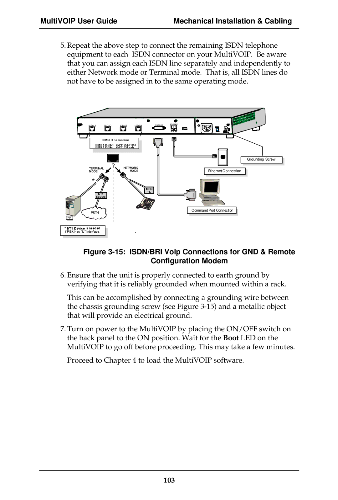
Cabling Procedure for MVP-410ST/810ST
101
102
103
104
Cabling Procedure for MVP210
105
JP1 Ch 2 Jumper Block
106
17 Cabling for MVP210
107
108
Cabling Procedure for MVP-130/130FXS
109
110
Software Installation
111
Loading MultiVOIP Software onto the PC
112
113
114
115
116
117
118
Un-Installing the MultiVOIP Configuration Software
119
120
121
MVP2410, MVP3010
122
Configuring the Digital T1/E1 MultiVOIP
123
124
Local Configuration
Pre-Requisites
IP Parameters
125
T1 Telephony Parameters for MVP2410
126
E1 Telephony Parameters for MVP3010
127
Smtp Parameters for email call log reporting
128
Local Configuration Procedure Summary
Local Configuration Procedure Detailed
130
131
Ctrl + G 132
Solving Common Connection Problems
133
134
Pulldown Icon Shortcut Sidebar
135
136
IP Parameter Definitions Field Name Values Description
137
Type of Service or TOS field
138
Default
139
140
Ctrl + H
141
142
143
Dtmf Parameters
Voice/Fax Parameter Definitions cont’d
When Dtmf Out of Band is
144
Voice/Fax Parameter Definitions cont’d Coder Parameters
146
Forward Error Correction enables
147
Alert
148
149
Optimization Factor
Modem Relay
150
151
Automatic Disconnection
Call Duration defines
Consecutive Packets Lost defines
152
Ctrl + T
153
154
155
T1 Parameter Definitions Field Name Values Description
RING-ON, RING-OFF
156
157
ISDN-PRI
158
159
Common will be 0 to 40m
160
161
E1 Parameter Definitions Field Name Values Description
MFR2 ANI
162
163
164
AMI / HDB3
165
166
167
Ctrl + M
168
Trap Manager Parameters
Snmp Parameter Definitions Field Name Values Description
169
170
Ctrl + R
171
172
Regional Parameter Definitions Field Name Values Description
173
T1 port. Default -16dB
Bring up the Custom Tone Pair
174
MultiVOIP User Guide Technical Configuration T1/E1
176
Tone Pair Values
177
178
Ctrl + Alt + S
179
180
Smtp Parameters Definitions Field Name Values Description
181
MultiVOIP User GuideTechnical Configuration T1/E1
182
Custom Fields Definitions Description
183
Custom Fields Definitions cont’d Description
184
185
Ctrl + Alt + O
186
Logs Screen Definitions Field Name Values Description
187
Logs Screen Definitions cont’d Field Name Values Description
188
189
Ctrl + Alt +H
190
191
192
193
Its Statistics Call Progress screen
Party, Busy Party, and Connected
194
Statistics Call Progress screen
Allowed Name Type, and Omaha
195
196
Supplementary Services screen
Field of the Statistics Call Progress
Identification has been enabled, Busy
197
An Allowed Name Type,
Supplementary Services
198
199
200
201
Ctrl + Alt +Y
202
203
204
MultiVOIP User Guide Technical Configuration T1/E1
206
207
Configuring the Analog/BRI MultiVOIP
208
Technical Configuration Analog/BRI MultiVOIP User Guide
209
210
211
212
ISDN-BRI Telephony Parameters For MVP-410ST/810ST
213
214
Local Configuration Procedure Detailed
216
217
Ctrl + G 218
219
220
221
222
223
IP Parameter fields
224
225
226
227
228
229
230
Not applicable to MVP130
231
Fax Volume
232
233
Voice/Fax Parameters Phone Number
234
235
Tone
236
Alert Timer Seconds
237
Jitter
238
239
240
Ctrl +
241
242
243
FXS
244
For Min. and Max
245
246
247
Field Name Values Description
FXO Interface Parameter Definitions
248
Dialing Options cont’d
249
FXO Disconnect On cont’d
250
Flash Hook Options fields
251
CID Name Melvin Jones Time Stamp Date 05/31 Time142pm
252
Time
253
Edwin Smith
254
255
256
Interface Parameter Definitions
#53 + PBX extension
257
258
259
Did Interface Parameter Definitions
Did Options cont’d
260
261
262
263
264
ISDN-BRI Parameter Definitions Field Name Values Description
ISDN-BRI Parameter Definitions
Switch Information
265
Type
266
267
Field Name Values Description MSN Details
268
269
270
271
272
273
274
16dB
275
MVP810ST
276
MultiVOIP User Guide Technical Configuration Analog/BRI
278
279
280
281
282
Technical Configuration Analog/BRIMultiVOIP User Guide
283
284
285
286
287
Filters button
288
289
290
291
292
293
294
295
296
Caller Id field
297
298
299
300
301
302
303
304
305
Technical Configuration Analog/BRI MultiVOIP User Guide
307
North American Telephony Standards
308
Configuring the MVP2410 MultiVOIP Phonebooks
309
MultiVOIP User Guide T1 PhoneBook Configuration
310
Phonebook Icons Description
311
312
Parameters
313
314
PhoneBook Configuration Parameter Definitions Cont’d
Version 4 Parameters
315
Version 4 Parameters
316
SIP Proxy Parameters
317
Field Name Values & Description
318
Cont’d Field Name Values Description
PhoneBook Configuration Parameter Definitions
319
320
Sec
321
About SPP Proxy/NAT Device Parameters
322
323
Add/Edit Outbound PhoneBook screen appears
Device is used . If Any
324
325
This field currently disabled
326
SIP Fields
327
SPP Fields
328
329
330
Alternate Routing Field Definitions Values Description Name
331
Add/Edit Inbound PhoneBook screen appears 332
333
When no external routing device is used . If
334
Destination
335
Sites, All-T1 Example
T1 Phonebook Examples
336
PBX
337
338
339
340
341
342
Configuring Mixed Digital/Analog Voip Systems
343
344
Phone Book for Series I Analog Voip Host Unit Site B
345
346
Outbound Phone Book for MVP2410 Digital Voip Site D
347
Inbound Phonebook for MVP2410 Digital Voip Site D
348
Outbound Phone Book for MVP410 Analog Voip Site F
349
Inbound Phonebook for MVP410 Analog Voip Site F
350
Outbound Phone Book for MVP210 Analog Voip Site E
Inbound Phonebook for MVP210 Analog Voip Site E
Call Completion Summaries
352
Site D calling Site C
353
Site D calling Site F
354
Variations in PBX Characteristics
355
European Telephony Standards
356
MVP3010 Inbound and Outbound MultiVOIP Phonebooks
357
Free Calls One Voip Site to Another
358
Local Rate Calls Within Local Calling Area of Remote
359
360
National Rate Calls Within Nation of Remote Voip Site
361
Inbound versus Outbound Phonebooks
362
363
364
Phonebook Configuration Procedure
365
366
367
368
369
370
371
372
373
374
375
376
377
378
379
Device is …
380
381
Alternate Routing Field Definitions Values Description Name
383
Add/Edit Inbound PhoneBook screen appears
384
385
Call Forward Parameters
386
Sites, All-E1 Example
E1 Phonebook Examples
387
388
France Country Code
Rotterdam
010
389
390
PBX
391
392
393
394
Configuring Digital & Analog VOIPs in Same System
395
Phone Book for Analog Voip Host Unit Site B
396
Channel Comments
397
Outbound Phone Book for MVP3010 Digital Voip Site D
398
Inbound Phone Book for MVP3010 Digital Voip Site D
399
400
401
402
Call Completion Summaries
Site a calling Site C, Method
Site C calling Site a
403
Site D calling Site C
404
405
406
International Telephony Numbering Plan Resources
407
408
Analog/BRI Phonebook Configuration
409
MultiVOIP User Guide Operation & Maintenance
410
Operation and Maintenance
System Information screen
Operation and Maintenance
411
412
Operation and Maintenance MultiVOIP User Guide
413
About Call Progress
Statistics Screens
414
415
Call Progress Details Screen
416
Call Details
417
Correction. Forward Error
418
Services Status
+ identifier
419
420
About Logs
Logs Screen
422
Special Buttons
423
From
424
IP Statistics Screen
About IP Statistics
425
Total Packets
IP Statistics Field Definitions Values Description Name
426
427
UDP
428
IP Statistics Field Definitions cont’d RTP Packets
Shortcut/Icon
About Link Management
429
430
431
Pulldown Shortcut/Icon
About Packetization Time
432
Packetization Ranges and Increments
Packetization Time Screen
433
434
435
About T1/E1 and BRI Statistics
436
T1 Statistics Screen
437
T1 Statistics Field Definitions Values Description Name
438
439
440
441
442
443
Isdn BRI Statistics Screen
444
Layer Interface
TEI Assignment
445
Isdn BRI Statistics Field Definitions
Field Values Description Name Switch Information
446
447
About Registered Gateway Details
448
449
MultiVoip Program Menu Items
MultiVOIP Program Menu
Menu Selection Description
450
MultiVOIP Program Menu cont’d Menu Selection Description
Configuration Port Setup
Configuration Option
451
Obtaining Updated Firmware
Date and Time Setup
452
453
454
455
Identifying Current Firmware Version
Implementing a Software Upgrade
456
457
Downloading Firmware
458
459
460
Downloading Factory Defaults
461
462
Downloading IFM Firmware Analog Voips only
463
464
465
466
Setting and Downloading User Defaults
467
468
Setting a Password Windows GUI
469
470
471
472
Setting a Password Web Browser GUI
473
Un-Installing the MultiVOIP Software
474
475
Upgrading Software
476
FTP Server File Transfers Downloads
477
Operation and Maintenance MultiVOIP User Guide
479
480
481
482
483
484
485
486
Web Browser Interface
487
488
489
490
491
SysLog Server Functions
492
MultiVOIP User Guide Operation & Maintenance
494
Regulatory Information
FCC Declaration
EMC, Safety, and R&TTE Directive Compliance
495
FCC Part 68 Telecom
Industry Canada
496
497
Canadian Limitations Notice
498
Appendix a Expansion Card Installation MVP24-48 & MVP30-60
499
Installation
500
Power Cable Molex Connector
501
Operation
502
Appendix B Cable Pinouts
503
Command Cable
Ethernet Connector
Appendix B Cable Pinouts
504
T1/E1 Connector
Voice/Fax Channel Connectors
T1/E1 Connector
505
506
Isdn BRI RJ-45 Pinout Information
507
Isdn Interfaces ST and U
508
Appendix C TCP/UDP Port Assignments
Port Number Assignment List
Well Known Port Numbers
509
510
511
Installation Instructions for MVP428 Upgrade Card
512
Channel Analog Expansion Card MultiVOIP User Guide
513
Screw locations 2 at phone-jack edge of board
514
Pin connectors
515
Index
516
Index MultiVOIP User Guide
517
207
518
BRI
519
136
520
521
522
523
524
525
ISDN-BRI
526
527
126
528
109
529
FRF11
530
138
531
MVP810ST
532
Version 4 Parameters
533
125
534
535
SPID1
536
537
538
Snmp
539
149
540
T1/ISDN
541
542
543
544
545
546
Except MVP130
547
RSG LED
548
134
549
550
551
296
552
553
Telecom safety warnings
554
555
556
113
557
123
558
XSG LED
559