Technical Specifications
The AN/DC and
•To connect a modem to the Console port, use the Order No. 110307 cable, a standard,
•To connect a terminal to the Console port, use the complete console/modem kit (the Order No. 110307 cable with the Order No.110308 null modem adapter).
•To connect an
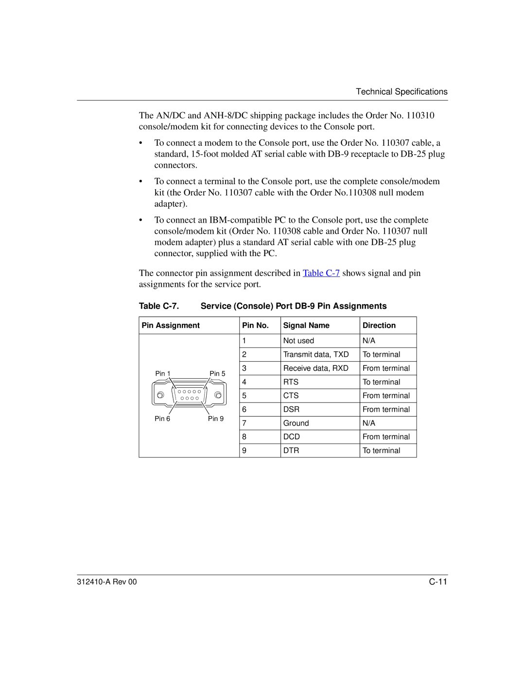
The connector pin assignment described in Table
Table C-7. Service (Console) Port DB-9 Pin Assignments
Pin Assignment |
| Pin No. | Signal Name | Direction | |
|
| 1 | Not used | N/A | |
|
| 2 | Transmit data, TXD | To terminal | |
Pin 1 | Pin 5 | 3 | Receive data, RXD | From terminal | |
4 | RTS | To terminal | |||
|
| ||||
|
| 5 | CTS | From terminal | |
|
| 6 | DSR | From terminal | |
Pin 6 | Pin 9 | 7 | Ground | N/A | |
|
| ||||
|
| 8 | DCD | From terminal | |
|
| 9 | DTR | To terminal |