Installing and Operating AN/DC and
ANH-8/DC LED Descriptions
LEDs on the
Front-Panel LEDs
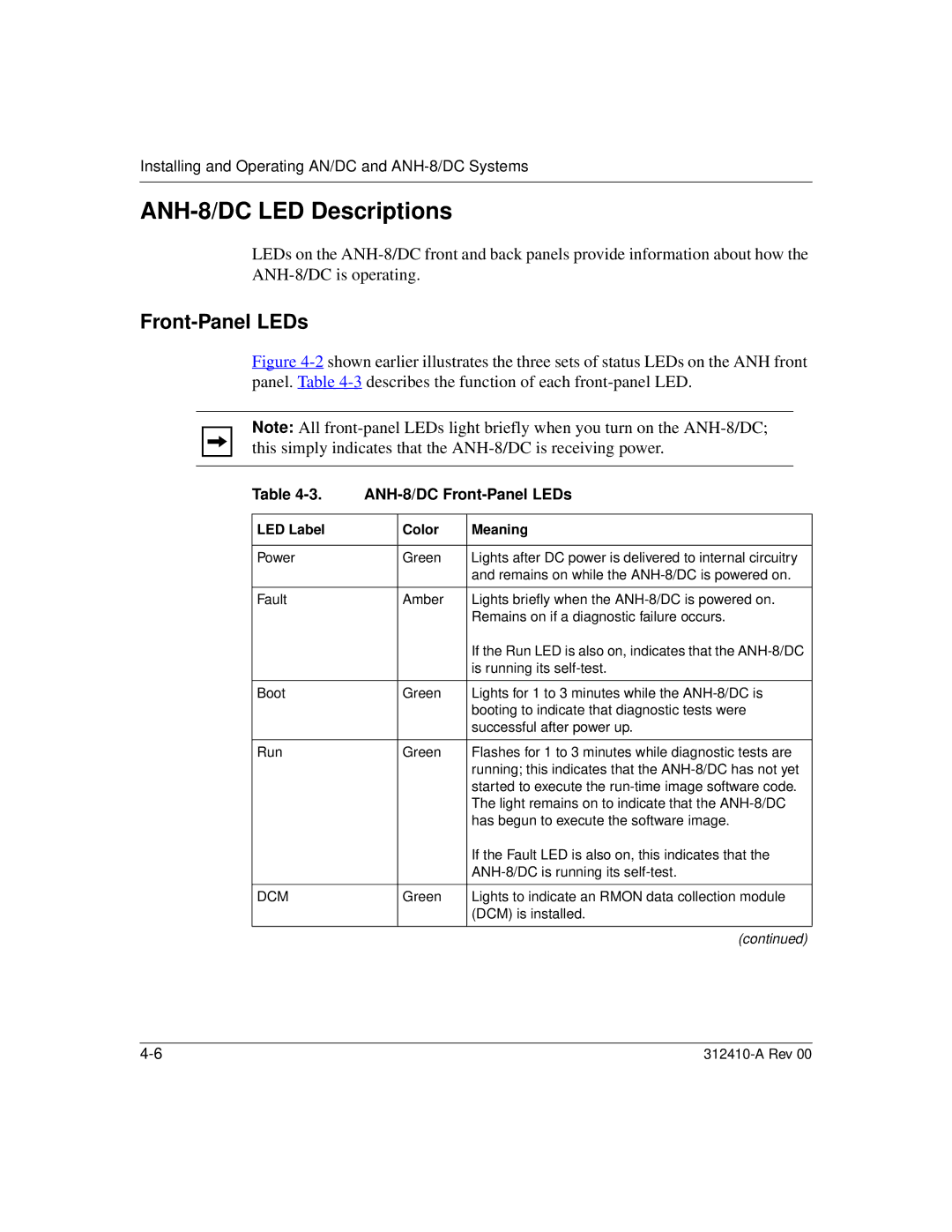
Figure 4-2 shown earlier illustrates the three sets of status LEDs on the ANH front panel. Table 4-3 describes the function of each front-panel LED.
Note: All
Table |
| ||
|
|
|
|
LED Label |
| Color | Meaning |
|
|
|
|
Power |
| Green | Lights after DC power is delivered to internal circuitry |
|
|
| and remains on while the |
|
|
|
|
Fault |
| Amber | Lights briefly when the |
|
|
| Remains on if a diagnostic failure occurs. |
|
|
| If the Run LED is also on, indicates that the |
|
|
| is running its |
|
|
|
|
Boot |
| Green | Lights for 1 to 3 minutes while the |
|
|
| booting to indicate that diagnostic tests were |
|
|
| successful after power up. |
|
|
|
|
Run |
| Green | Flashes for 1 to 3 minutes while diagnostic tests are |
|
|
| running; this indicates that the |
|
|
| started to execute the |
|
|
| The light remains on to indicate that the |
|
|
| has begun to execute the software image. |
|
|
| If the Fault LED is also on, this indicates that the |
|
|
| |
|
|
|
|
DCM |
| Green | Lights to indicate an RMON data collection module |
|
|
| (DCM) is installed. |
|
|
|
|
|
|
| (continued) |