Installing and Operating AN/DC and
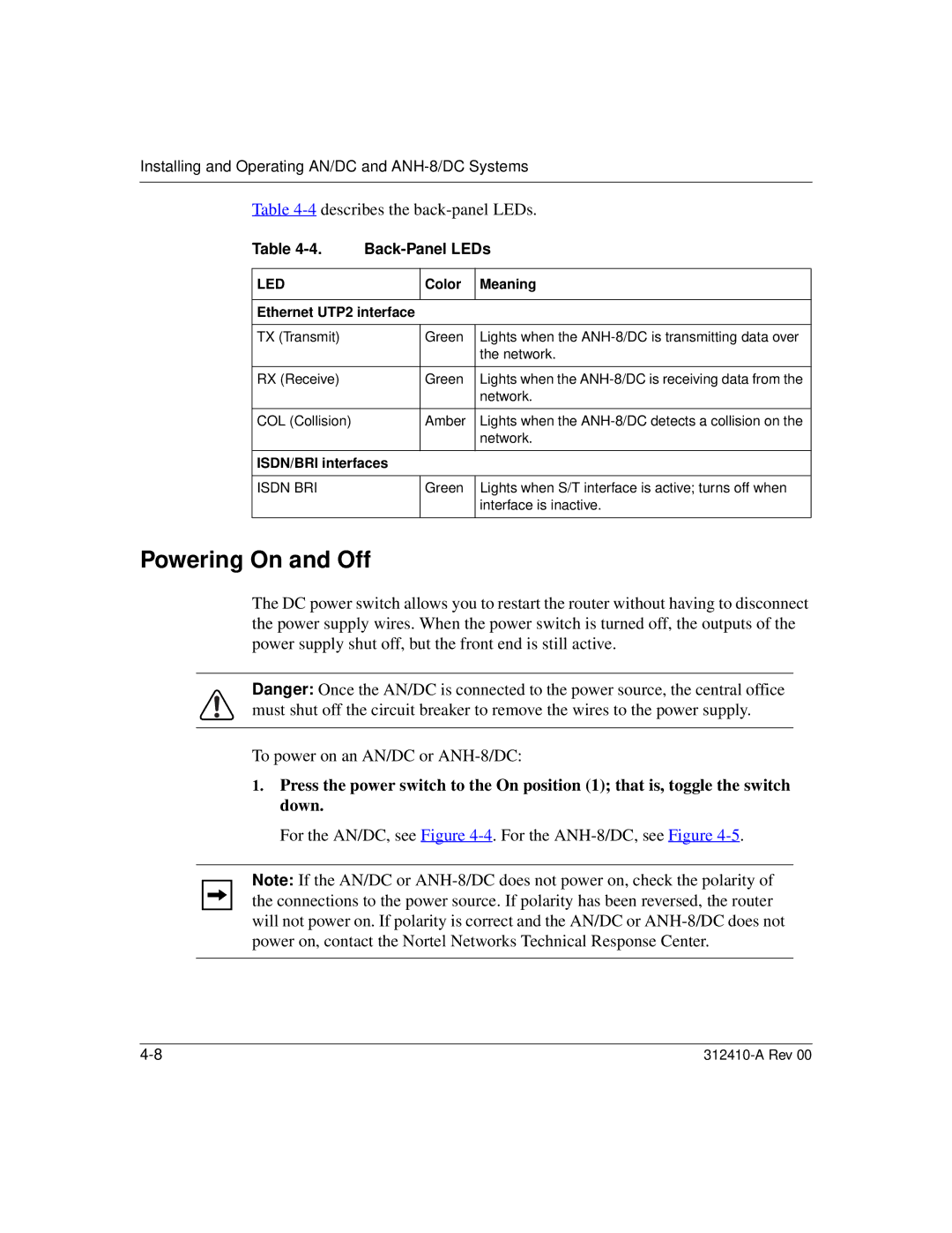
Table 4-4 describes the back-panel LEDs.
Table |
| ||
|
|
|
|
LED |
| Color | Meaning |
|
|
| |
Ethernet UTP2 interface |
| ||
|
|
|
|
TX (Transmit) |
| Green | Lights when the |
|
|
| the network. |
|
|
|
|
RX (Receive) |
| Green | Lights when the |
|
|
| network. |
|
|
|
|
COL (Collision) |
| Amber | Lights when the |
|
|
| network. |
|
|
| |
ISDN/BRI interfaces |
| ||
|
|
|
|
ISDN BRI |
| Green | Lights when S/T interface is active; turns off when |
|
|
| interface is inactive. |
|
|
|
|
Powering On and Off
The DC power switch allows you to restart the router without having to disconnect the power supply wires. When the power switch is turned off, the outputs of the power supply shut off, but the front end is still active.
Danger: Once the AN/DC is connected to the power source, the central office must shut off the circuit breaker to remove the wires to the power supply.
To power on an AN/DC or
1.Press the power switch to the On position (1); that is, toggle the switch down.
For the AN/DC, see Figure 4-4. For the ANH-8/DC, see Figure 4-5.
Note: If the AN/DC or