Installing the AN/DC
3.Strip 3/8 in. (10 mm) of insulation from the end of a #16 or #18 AWG cable.
Note: Although #18 AWG cable is adequate, we recommend #16 AWG cable to ensure minimal voltage drop from the power source.
4.Insert the stripped end of the cable into the
5.Tighten the screw beneath the
UL
UL
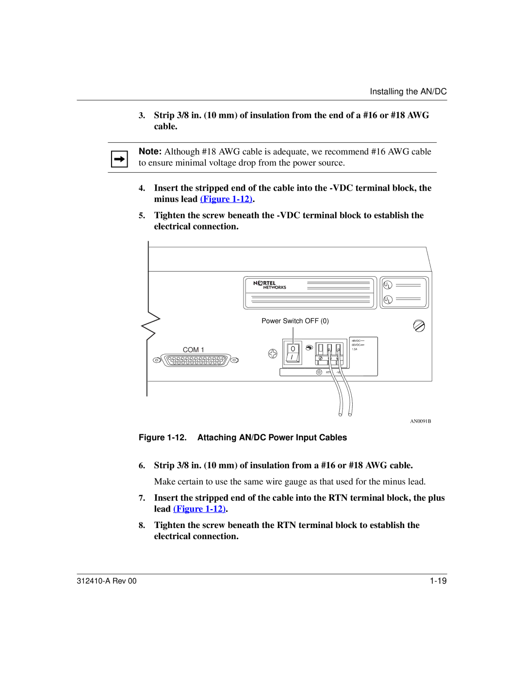
Power Switch OFF (0)
COM 1
![]()
1.5A
RTN
AN0091B
Figure 1-12. Attaching AN/DC Power Input Cables
6.Strip 3/8 in. (10 mm) of insulation from a #16 or #18 AWG cable. Make certain to use the same wire gauge as that used for the minus lead.
7.Insert the stripped end of the cable into the RTN terminal block, the plus lead (Figure
8.Tighten the screw beneath the RTN terminal block to establish the electrical connection.