Installing the AN/DC
Connecting Communications Cables
To connect network cables to the back of the AN/DC:
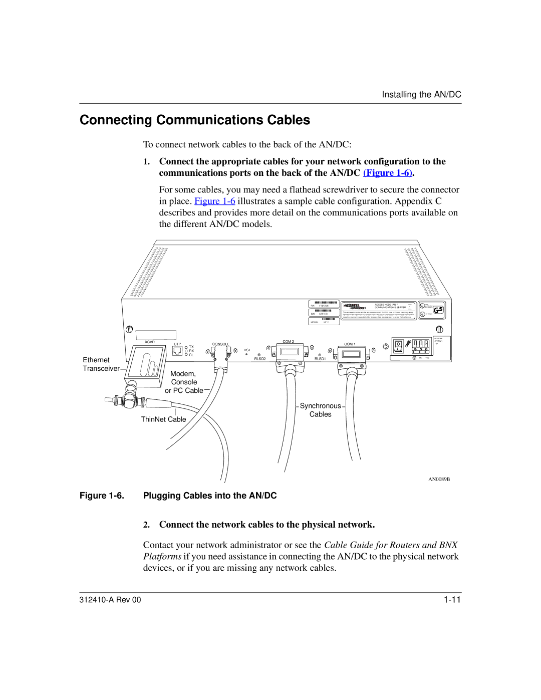
1.Connect the appropriate cables for your network configuration to the communications ports on the back of the AN/DC (Figure
For some cables, you may need a flathead screwdriver to secure the connector in place. Figure
P/N |
|
| ACCESS NODE (AN) TM | MADE |
| ||
| |||||||
|
| COMMUNICATIONS SERVER | IN |
| |||
|
|
|
| U.S.A. |
| ||
|
|
|
|
|
|
|
|
S/N | ATX15¯8 | This equipment complies with the requirements in part 15 of FCC rules for Class A computing device |
| ||||
Operation of the equipment in a residential area may cause unacceptable interference to radio and TV |
| ||||||
|
| reception requiring the operator to take whatever steps are nessessary to correct the interference. |
| ||||
|
|
|
|
|
|
|
|
MODEL 22¯¯2
XCVR | UTP | CONSOLE | COM 2 |
| COM 1 | ||
|
| TX | RST |
|
| RX | |
|
| CL |
|
Ethernet | RLSD2 | RLSD1 |
| ||
Transceiver |
|
|
Modem,
Console
or PC Cable
Synchronous
Cables
ThinNet Cable
S403
UL LISTED EDP
EQUIPMENT
UL L6 4490313
![]()
1.5A
RTN
AN0089B
Figure 1-6. Plugging Cables into the AN/DC
2.Connect the network cables to the physical network.
Contact your network administrator or see the Cable Guide for Routers and BNX Platforms if you need assistance in connecting the AN/DC to the physical network devices, or if you are missing any network cables.