Installing and Operating AN/DC and
Connecting Synchronous Cables
Connect one to three synchronous interface cables to the back of the
1.Locate the
2.Connect the cable to the
Note: Your
COM3/Expansion port may be empty or contain another cable interface.
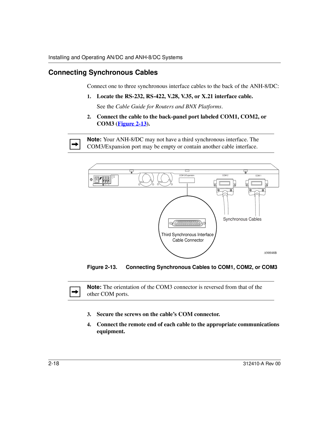
COM 3/Expansion | COM 2 | COM 1 | |
|
|
| |
1.5A |
|
|
|
RTN
Synchronous Cables
Third Synchronous Interface
Cable Connector
AN0048B
Figure 2-13. Connecting Synchronous Cables to COM1, COM2, or COM3
Note: The orientation of the COM3 connector is reversed from that of the other COM ports.
3.Secure the screws on the cable’s COM connector.
4.Connect the remote end of each cable to the appropriate communications equipment.