|
|
|
| Operating the AN/DC and |
|
|
|
|
|
| Table |
| ||
|
|
|
|
|
| LED Label |
| Color | Meaning |
|
|
|
|
|
| AUI Part |
| Amber | Lights to indicate that the AUI port has been |
| (Partition) |
|
| partitioned from the repeater due to a disruption in |
|
|
|
| transmission. Autopartitioning occurs after an |
|
|
|
| excessive number of consecutive collisions or an |
|
|
|
| excessively long |
|
|
|
| |
| DCD1 (Data Carrier | Green | Lights to indicate that the first synchronous port | |
| Detect 1) |
|
| (COM1) is active. |
|
|
|
| |
| DCD2 (Data Carrier | Green | Lights to indicate that the second synchronous port | |
| Detect 2) |
|
| (COM2) is active. |
|
|
|
|
|
| <LAN> |
| Green | Lights after each data transmission to indicate data |
|
|
|
| present in the repeater. The signal is longer than the |
|
|
|
| duration of data, allowing the eye to perceive the |
|
|
|
| occurrence of very short transmissions. The LED may |
|
|
|
| appear to flicker during numerous transmissions. |
|
|
|
|
|
| Col |
| Amber | Lights to indicate a collision in the AUI repeater. |
| (Collision) |
|
|
|
|
|
|
|
|
Back-Panel LEDs
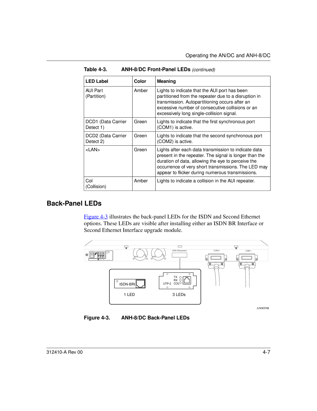
Figure 4-3 illustrates the back-panel LEDs for the ISDN and Second Ethernet options. These LEDs are visible after installing either an ISDN BR Interface or Second Ethernet Interface upgrade module.
![]()
1.5A
RTN
![]()
![]()
COM 3/Expansion | COM 2 |
| COM 1 | |
|
|
|
|
|
|
|
|
|
|
|
|
|
|
|
|
|
|
|
|
TX
RX
![]()
1 LED | 3 LEDs |
AN0059B
