Installing and Operating AN/DC and
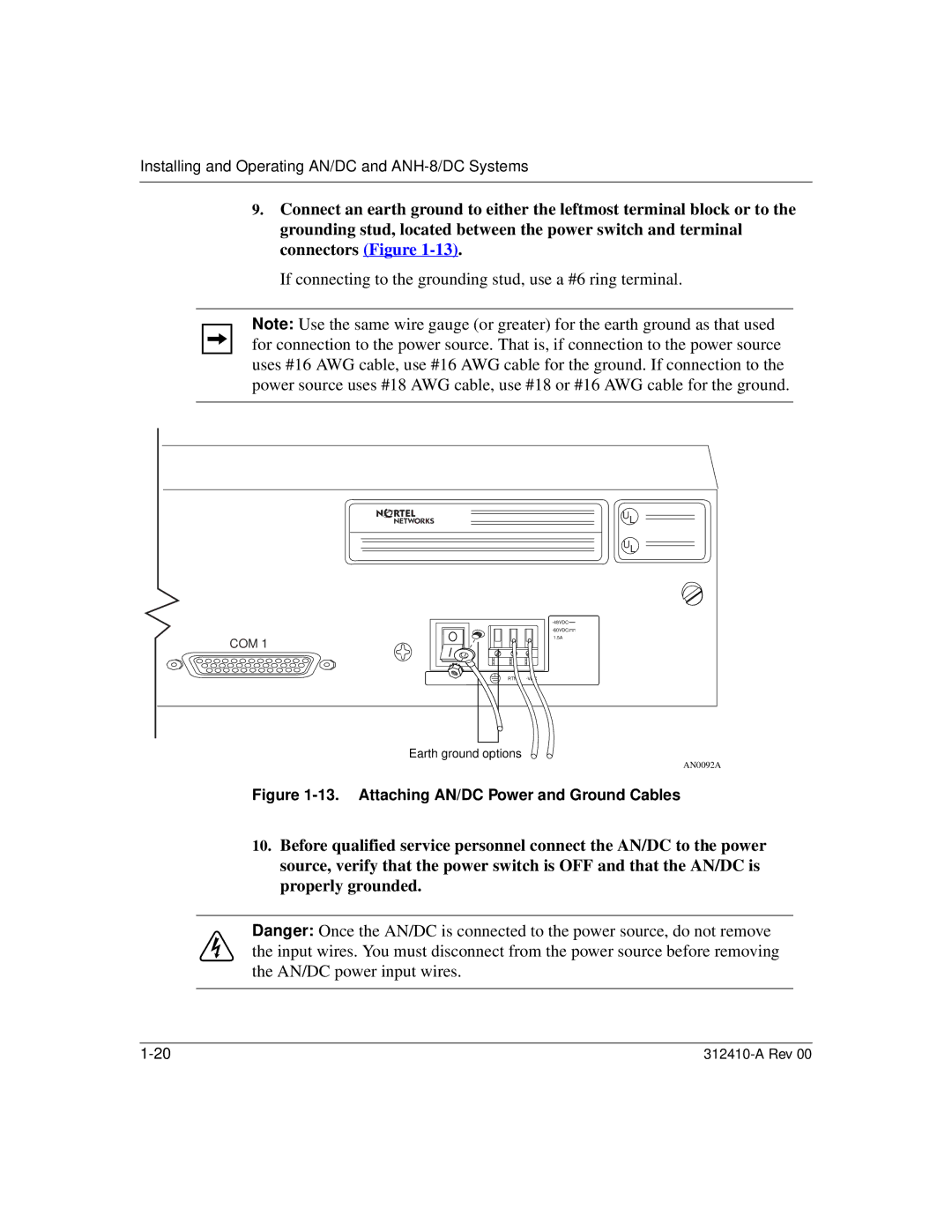
9.Connect an earth ground to either the leftmost terminal block or to the grounding stud, located between the power switch and terminal connectors (Figure
If connecting to the grounding stud, use a #6 ring terminal.
Note: Use the same wire gauge (or greater) for the earth ground as that used for connection to the power source. That is, if connection to the power source uses #16 AWG cable, use #16 AWG cable for the ground. If connection to the power source uses #18 AWG cable, use #18 or #16 AWG cable for the ground.
UL
UL
COM 1
![]()
1.5A
RTN
Earth ground options
AN0092A
Figure 1-13. Attaching AN/DC Power and Ground Cables
10.Before qualified service personnel connect the AN/DC to the power source, verify that the power switch is OFF and that the AN/DC is properly grounded.
Danger: Once the AN/DC is connected to the power source, do not remove the input wires. You must disconnect from the power source before removing the AN/DC power input wires.