|
|
|
|
| Requirements for European Operation |
|
|
|
|
| |
| Table | ISDN BRI Clearances and Creepage Distances | |||
|
|
|
|
|
|
|
|
|
|
| Voltage used or generated by other parts |
| Clearance (X) |
| Creepage (Y) | of the host or expansion card | |
|
|
|
|
| |
| 2.0 mm |
| 2.4 (3.8) mm | Up to 50 V rms or V dc | |
|
|
|
|
|
|
| 2.6 mm |
| 3.0 | (4.8) mm | Up to 125 V rms or V dc |
|
|
|
|
|
|
| 4.0 mm |
| 5.0 | (8.0) mm | Up to 250 V rms or V dc |
|
|
|
|
|
|
| 4.0 mm |
| 6.4 | (10.0) mm | Up to 300 V rms or V dc |
|
|
|
|
|
|
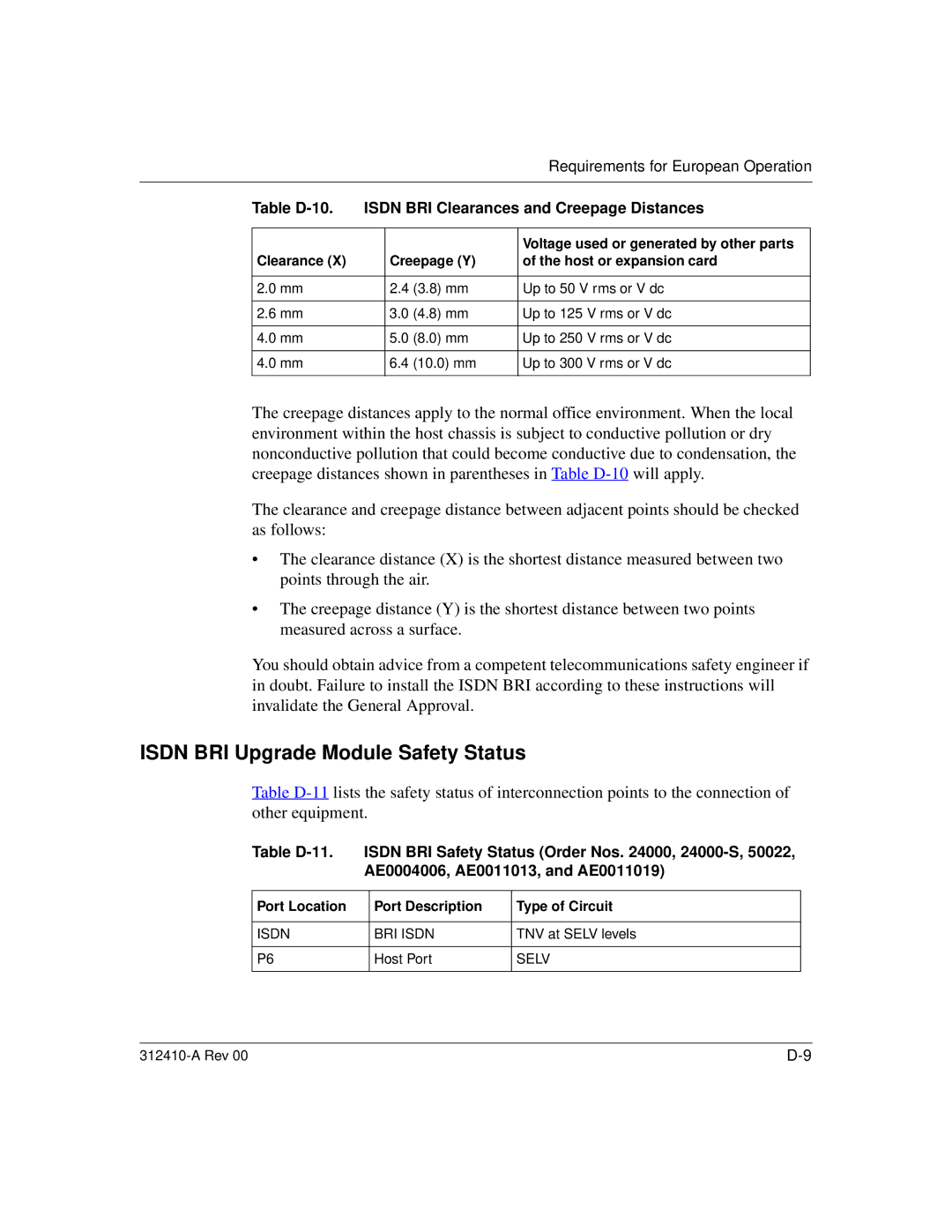
The creepage distances apply to the normal office environment. When the local environment within the host chassis is subject to conductive pollution or dry nonconductive pollution that could become conductive due to condensation, the creepage distances shown in parentheses in Table
The clearance and creepage distance between adjacent points should be checked as follows:
•The clearance distance (X) is the shortest distance measured between two points through the air.
•The creepage distance (Y) is the shortest distance between two points measured across a surface.
You should obtain advice from a competent telecommunications safety engineer if in doubt. Failure to install the ISDN BRI according to these instructions will invalidate the General Approval.
ISDN BRI Upgrade Module Safety Status
Table
Table | ISDN BRI Safety Status (Order Nos. 24000, | ||
| AE0004006, AE0011013, and AE0011019) | ||
|
|
|
|
Port Location |
| Port Description | Type of Circuit |
|
|
|
|
ISDN |
| BRI ISDN | TNV at SELV levels |
|
|
|
|
P6 |
| Host Port | SELV |
|
|
|
|
